repairing a Supernova Triple dynamo headlight

Steve K

Flashlight Enthusiast
Joined
Jun 10, 2002
Messages
2,786
Location
Peoria, IL
I just completed work on a Supernova Triple headlight, and thought the CPF crowd (or at least this little corner of CPF) might find it interesting. I've got a number of photos and am working on writing up the story of what happened. Here's Chapter 1 for your entertainment.

chapter 1. disassembly

a fellow on a bike forum asked for help with a Supernova Triple
dynamo light. I'd been curious about these lights, so I offered to try
to fix it if he would cover the cost of the parts and the shipping. He
had gotten the light for free (someone else had damaged it), so he
agreed. My assumption was that the failure was probably a broken
wire or some other obvious damage, so it shouldn't be too hard to
repair. I did mention to the owner that it could be damage that just
couldn't be repaired by anyone but the factory, though.

I've finished working on the light and thought that this group might
enjoy seeing how the light is built and some of the troubleshooting
and repair(?) process. For the sake of drama and interest, I don't
want to tell you how the story ends, but would prefer to let the story
unfold.

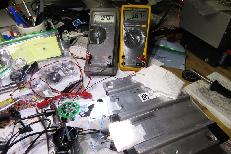
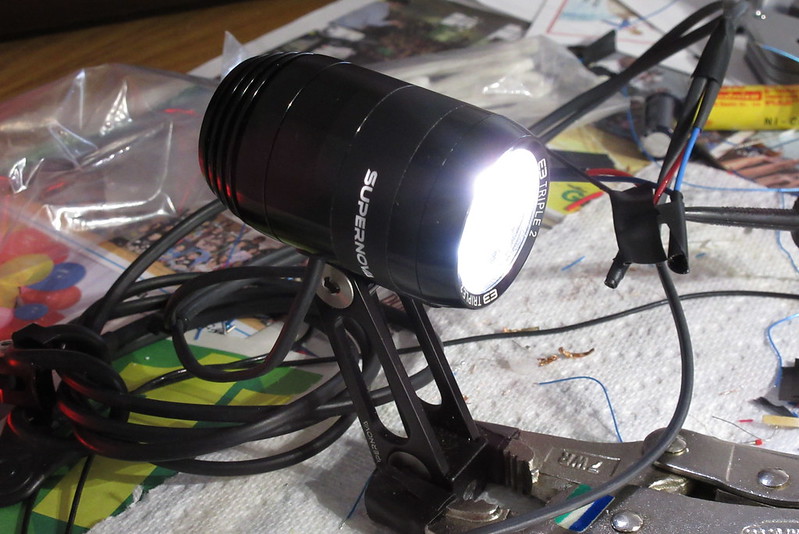
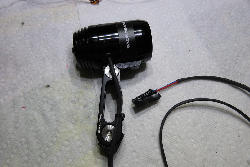
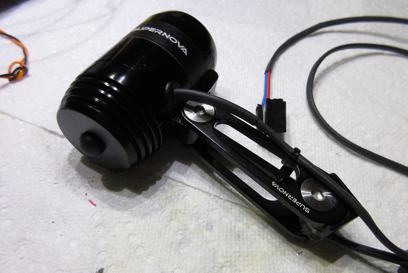
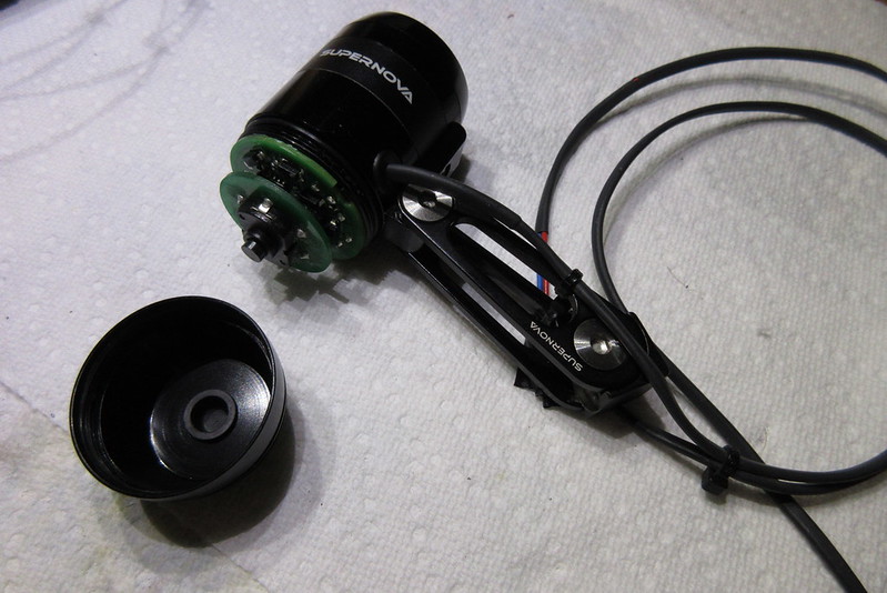
The light is housed in a very nice aluminum body with a bracket of
similar quality. Even if all of the electronics was dead, it would
make a nice host for a design of one's own.

32669720820_ed654f0641_c_d.jpg


32895943352_d1959227a4_c_d.jpg


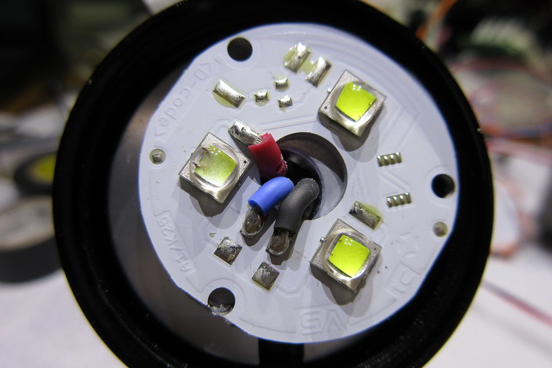
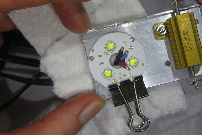
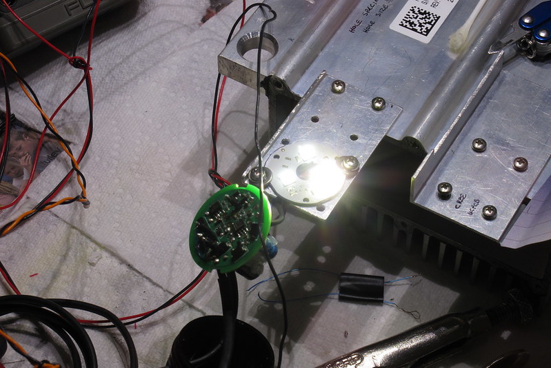
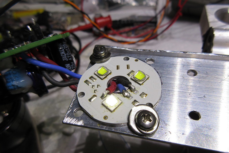
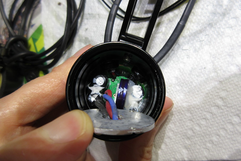
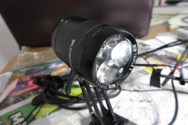
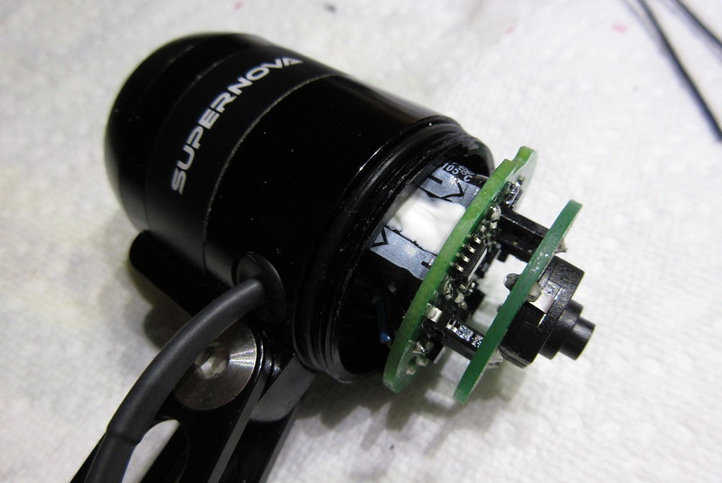
The light has a front bezel that unscrews, revealing the triple optics
and the LED MCPCB (Metal Core Printed Circuit Board). At the
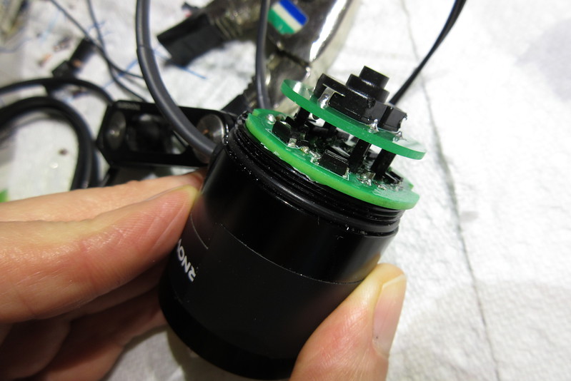
rear of the light is a screw-on cap, which has a boot for the push
switch, and which covers the circuit boards.

32895940882_0b2032148c_c_d.jpg


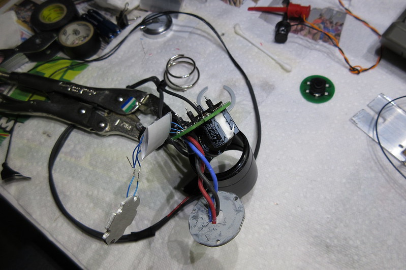
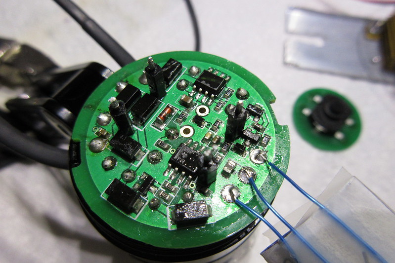
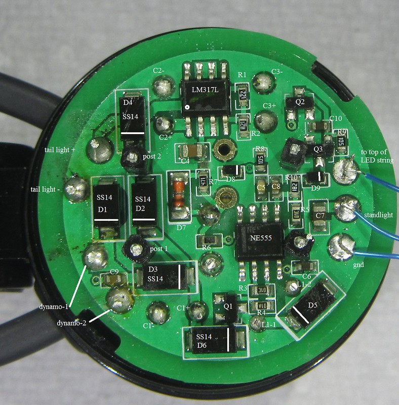
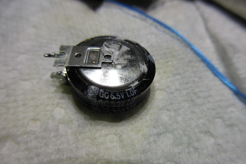
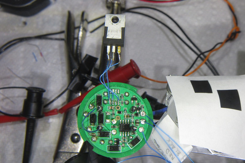
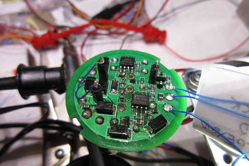
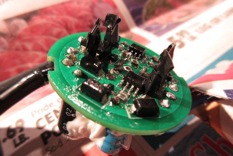
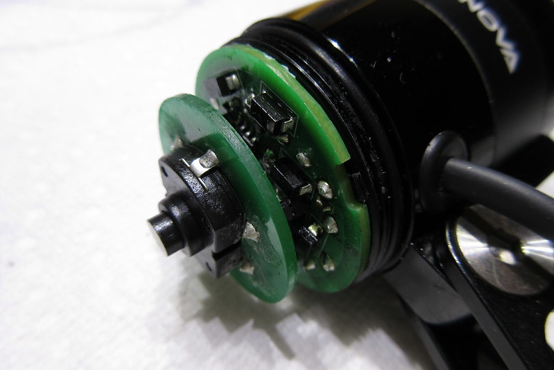
There are two circuit boards. The small board has just one
component.... the push switch. The large board has the rest of the
components. The boards are both built well... fairly thick, to
handle the force of actuating the push switch.

The lower board has conformal coating to resist moisture. Overall, they looked like they
were high quality, which matches the rest of the light.

32895937922_b7fe929d61_c_d.jpg


32895935952_a79caec0f0_c_d.jpg


32895933382_0fff3df2da_c_d.jpg


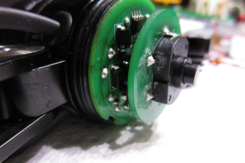
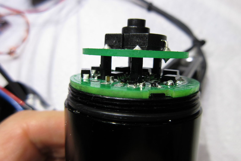
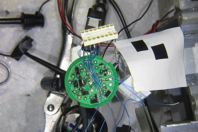
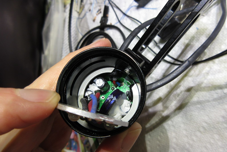
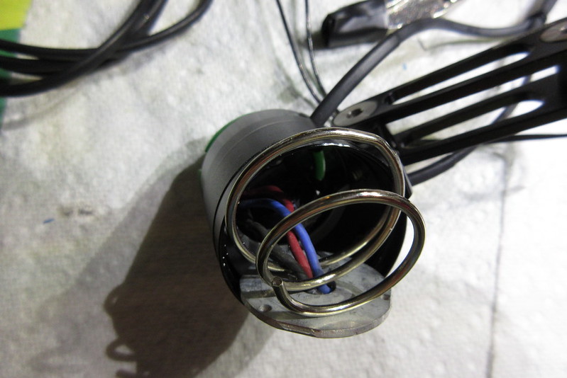
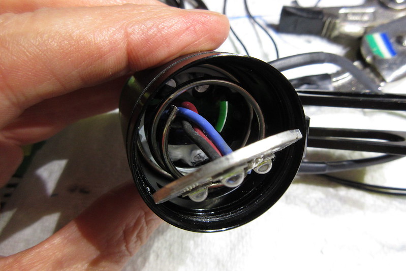
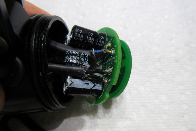
It took a bit of head scratching before I figured out how to get
access to the bottom of the lower circuit board. There is one wire
pair that goes to the dynamo, and one wire pair that goes to the
taillight. By sliding these wires through their grommets and into the
housing, there was enough slack in the wires to slide the circuit
board partly out of the housing. The board was still restrained by
the three wires going to the LED MCPCB.

32895931082_dc94115f1d_c_d.jpg


32236511413_915c276d8d_c_d.jpg


32925324021_27ca16147e_c_d.jpg


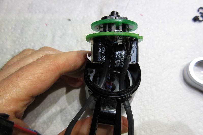
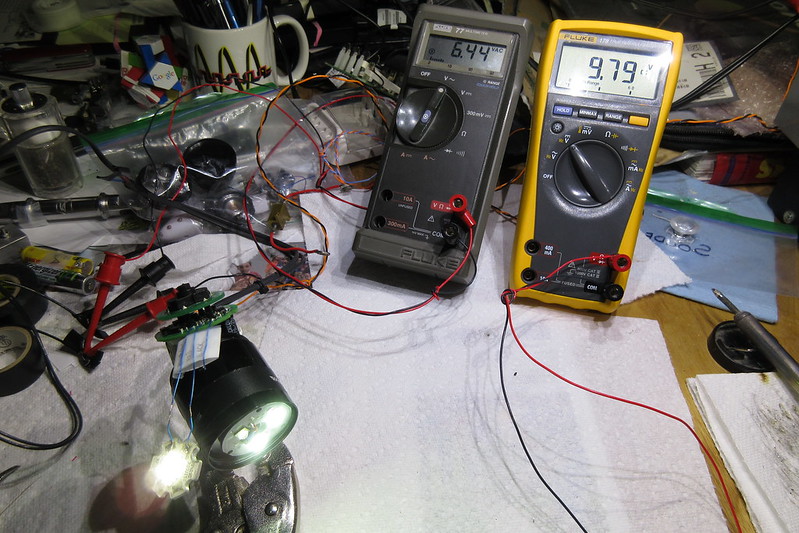
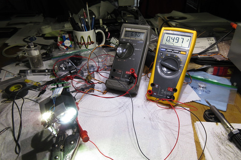
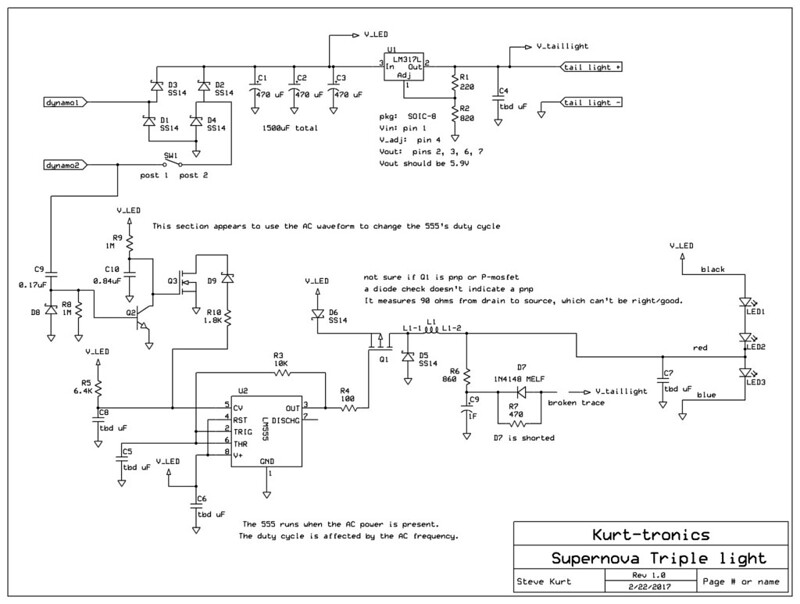
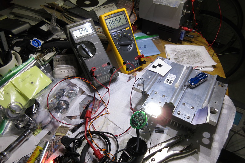
My hopes of finding a simple broken wire were ruined, so now I
had to actually do some work and figure out what was wrong with
the light.

.... to be continued.... (in next post)
 

Steve K

Flashlight Enthusiast
Joined
Jun 10, 2002
Messages
2,786
Location
Peoria, IL
a little drama can be a good thing. :)

plus, it avoids the "too long, didn't read" problem.

of course, the real reason for breaking it into chapters is that I'm still working on writing the story!
 

abvgdee

Newly Enlightened
Joined
Jun 25, 2014
Messages
49
For the sake of drama and interest, I don't want to tell you how the story ends, but would prefer to let the story unfold.
'No, no! The adventures first,' said the Gryphon in an impatient tone: 'explanations take such a dreadful time.' :)

Is it the "E3 Triple"? The blinding one - for off-road? (I'm mainly interested in road - StVZO lighting)
 

Steve K

Flashlight Enthusiast
Joined
Jun 10, 2002
Messages
2,786
Location
Peoria, IL
the bezel does/did say E3 triple 2. The beam is too wide for road use, IMHO. It uses XML LEDs, combined with a relatively small triple optic, so there is no way it could ever be a narrow beam. It is pretty darned bright! Even considering that it is running at 4.5W, it is pretty bright! Not my cup of tea, in regards to the beam, but the engineering quality is quite good. The electronics design is rather quirky, at least to me (this will be revealed in a couple of days. :) )
 
Last edited:

Steve K

Flashlight Enthusiast
Joined
Jun 10, 2002
Messages
2,786
Location
Peoria, IL
Chapter 2. Signs of Damage to the LEDs


One rule of troubleshooting is to always check the easy stuff first. i.e. "is it plugged in?" For the Supernova, since all of the electronics was covered by the push switch circuit board, it seemed reasonable to look at the LEDs and their operation. Conveniently, the three wires going to the MCPCB had pads on the edge of the board, where they could be easily reached!

I tacked some short lengths of 30 gauge wire to the pads of the LED wires. This made it easier to attach multimeter leads.

My test setup is pretty basic. Instead of spinning a dynamo to power the light, I've got a sine wave generator that provides a low frequency sine wave, as well as an inverted version of the sine wave. These two signals are fed into an audio amplifier, and these two outputs act as the simulated dynamo terminals.

Typically, I set up the sine wave frequency for 40Hz, which is a modest cruising speed with my SON dynamos (15mph or so? I'd have to check my data). I adjust the amplifier gain to provide the desired current through the light. If I'm looking for a more accurate simulation, I do have a large inductor and a 2 ohm power resistor that I connect in series with the amplifier output, which simulates the dynamo's internal impedances.

Powering the light, I was able to measure a total of 8.9VDC across the string of 3 LEDs. The lowest LED had 4.16VDC across it, and was glowing dimly. The upper two LEDs were not glowing at all. This suggested that the lower LED had a high resistance, which didn't leave enough voltage to forward bias the upper LEDs.

Getting the lower LED off of the MCPCB would be difficult, so the easy thing to do was to tack another white 3W LED in parallel with the lower LED.

Here's a shot of the MCPCB and LEDs...

33011165406_708b6ef69f_c_d.jpg


Oddly, the black wire is the voltage at the top of the string and the blue wire is the ground connection. The red wire is for the standlight, powering just the lower LED. Most color conventions (that I know of) would use red for the main voltage and black for the ground connection.

and a shot of the extra white LED tacked on.....

32237552543_fd7b0d9106_c_d.jpg


The meter on the left shows the voltage applied to the light. The light is running at low power, since I didn't have a heatsink on the extra LED.

Kludging up a heatsink for the extra LED, I was able to run the light at 0.5A AC, with the light's upper two LEDs lighting up quite nicely.
For reference, the dimensions of the Supernova's LEDs are 5mm x 5mm. This matches the Cree XM-L2. This is a 3V LED, rated for 3A. This would be a suitable replacement.

33053012975_8ea274b90c_c_d.jpg


This was very good news!
However, once I turned off the power, there was no standlight. Rats!
It looked like I would have to dig into the circuit and figure out how the standlight worked.
 

Steve K

Flashlight Enthusiast
Joined
Jun 10, 2002
Messages
2,786
Location
Peoria, IL
Chapter 3. Troubleshooting and Reverse Engineering the Circuit.

Curiously, the first step to figuring out the circuit was to figure out how to get the MCPCB out of the housing! The wires connecting the circuit board to the MCPCB were too short to get complete access to the circuit board.

Behind the MCPCB is an aluminum piece that provides a path for the heat to flow from the MCPCB to the light's housing. It has a slot in the circular part, running from the center to the edge. This allows it to be removed without detaching the wires. Very handy!

Behind the aluminum heat path is a coiled spring. This spring provides the force to keep the aluminum heat path in close contact with the MCPCB. With some care, the spring can be "threaded" around the wires and removed.

Behind the spring is a washer with a slot in it. It rests on a lip in the housing's inner circumference, and provides a base for the spring to push against. This washer is relatively easy to remove too.

With all of those parts gone, the MCPCB can be carefully fed through to the rear of the housing, allowing full access to the circuit board and MCPCB! Very helpful!

32903429572_30a69f0428_c_d.jpg


The next step was to remove the switch circuit board. It is mounted on 4 posts, and required either fully desoldering the posts, or incrementally heating the pad for each post and lifting that part of the board slightly. I don't have success with completely desoldering through-hole parts, so I reluctantly used the second option. Repeatedly heating a pad can damage a cheaper board, but this board handled it with no apparent affect.

With the switch board removed, I got a look at the circuit....

32932867351_4b8bb9774a_c_d.jpg


As you can see, there's no part that is obviously damaged, which makes the troubleshooting a little more work. On the plus side, it's hard to identify the part number of a chip that is now just a black smudge on the board!

A quick look at the board shows that it is conformal coated, which resists the effects of moisture. From what I've heard, at least one large manufacturer of dynamo lights doesn't protect the circuit from moisture, so kudos to Supernova for this extra detail!

Looking at the parts on the board, you can see that there are a number of discrete components, and only two integrated circuits. A close look at the ICs reveals that one is a LM317L voltage regulator, and the other is a NE555 timer. This is good news, because these are some of the most common parts in existence! I was worried that the light might use a little microcontroller running some custom software. This would be a part that would be impossible for me to replace. With the standard parts, I had a decent chance of fixing it.

My initial estimate was that the circuit used a group of rectifier diodes to form a full wave rectifier, converting the AC to DC. To get a full understanding of the circuit, I quickly had to get out my multimeter and probes and start finding out what was connected to what. This is a rather tedious bit of work, but there aren't many alternatives when you don't have the schematic or at least the gerber files for the circuit board.

After much work, I was able to create a schematic for the circuit and made notes on the image of the circuit board.....

schematic:
33017901146_0fb78fa252_c_d.jpg


annotated board photo:
32677628660_0d11812f2b_c_d.jpg


A quick summary of the function of the various parts of the circuit:

Bridge rectifier:
composed of D1 through D4, with output filter capacitors C1, C2, and C3. The filtered output is used to power the series string of LEDs, as well as providing power to the taillight's voltage regulator.

Taillight voltage regulator:
U1 is a LM317L voltage regulator. It reduces the output of the bridge regulator to 5.9V, which is used to power the taillight. R1 and R2 set the voltage that the LM317L will regulate at. The taillight voltage is also used to quickly charge the supercapacitor, which provides power for the standlight function.

Standlight circuit:
This is a very basic standlight circuit. D7 allows the supercapacitor, C9, to be charged quickly by the taillight voltage. When the dynamo voltage is gone, the supercapacitor will power the taillight and lower LED. The current to the taillight is limited by R7. Similarly, the current to the lower LED is limited by R6.

Buck converter:
A buck converter is a circuit that converts a high voltage to a low voltage by means of an energy storage element. The arrangement is fairly typical for a buck converter. U2 is a NE555 oscillator that drives a switch transistor, Q1. When Q1 is on, current from the bridge rectifier passes through L1, which stores energy in the form of a magnetic field. When Q1 is off, the magnetic field in L1 is converted to current, allowing current to flow through D5 and the lower LED in the string of LEDs.

I didn't go into great detail when reverse engineering the 555 oscillator circuit. Mostly, I did enough to be convinced that it would oscillate. My initial assumption was that it was operating as a brief, but high power, standlight. The group of components that include Q2, Q3, D8, and D9 seemed to be a simple circuit to detect when AC power was present. My guess was that it pulled the voltage threshold for the 555's comparators low enough that it wouldn't oscillate when the dynamo was running.

Instead, I later realized that the 555 ran whenever AC power was present and didn't provide any standlight function. It seems that the circuit is intended to adjust the 555's duty cycle as the dynamo's frequency varies.
 

mbanzi

Newly Enlightened
Joined
Nov 2, 2015
Messages
37
Fantastic work Steve! Will be an interesting exercise to try and build that circuit...
 

Steve K

Flashlight Enthusiast
Joined
Jun 10, 2002
Messages
2,786
Location
Peoria, IL
Fantastic work Steve! Will be an interesting exercise to try and build that circuit...

Thanks! :)
The buck converter and the "AC detector" are definitely intriguing! It meshes well with my interest in MPPT (maximum power point tracking/tracker) designs. It's been a while since I've done any microcontroller work, so it is easiest for me to implement something with analog circuits at this time. The 555 is a nice part that offers a lot of ways to get clever with it.

The "AC detector" circuit seems to provide a variable current sink that is a function of frequency. No idea how linear it is, or how easy it is to adjust it. I had thought about this sort of concept before, but always assumed that it would require a one-shot to get a reasonably linear relationship between the frequency and an output voltage or current.

It would take a little work to do the math and figure out what sort of transfer function the circuit should have, i.e. what should the duty cycle be for each dynamo frequency, and then how do you get it, but it's an interesting problem. :)

I looked up Supernova's web site yesterday and noticed that they are only producing lights with a single LED. Given how powerful the current LEDs are, this makes sense. Plus, it provides the option of producing a narrow beam. They must be using a buck converter... although there are 6V LEDs, which would make possible a very simple electronic design. The Cree XHP-70 is an example, although it offers the choice between being configured for 6V or 12V use.
 

Steve K

Flashlight Enthusiast
Joined
Jun 10, 2002
Messages
2,786
Location
Peoria, IL
Chapter 4. Repair Work and Reassembly

The first dead component that I found was D7. While reverse engineering the circuit, I noticed that D7 was shorted. This is not uncommon in diodes that exceed their power rating. When D7 was removed, the short was gone, indicating that it wasn't a failure of R7 or debris on the board. About this time, I realized that there was a damaged trace that connected D7 & R7 to the output of the LM317L. This was another sign of a very large amount of current passing through these parts.

32677849380_0b209489ca_c_d.jpg


After removing D7, I could see that the LM317L wasn't working. The output was only 0.23V. At the same time, I wasn't getting a good reading on the impedance of the supercapacitor. It only measured 5.6uF, while it should have been 1F.

I desoldered the supercap from the rear of the board. Once it was out, it became obvious that it was bulged, which is a sign of a failure due to overcharging.

32933320401_240a9211a7_c_d.jpg


For the sake of continuing troubleshooting, I installed a 1000uF electrolytic cap in its place.

At this time, I removed the apparently damaged LM317L and tacked in a LM317 in a TO-220 package. It's a different package, but is good enough for troubleshooting. With the new LM317, the taillight powers up properly.

32904002222_e13f4eec34_c_d.jpg


I wanted to replace D7, but really didn't know if it was silicon or perhaps a schottky diode. It could have been a zener too, but there didn't seem to be a reason for that. One of my concerns was limiting the charge voltage of the supercapacitor. Feeding 5.9V from the taillight regulator into a 5.5V supercap didn't seem like a good idea, even with the voltage drop across the D7 diode. The issue is that the voltage drop across the diode changes with current. Once the supercap gets close to fully charged and the charge current decreases, the voltage across the diode decreases too. This means that the supercap charge could end up very close to 5.9V. Granted, the resistor R6 will be conducting some current to the lower LED, so there should always be some current through D7. To be conservative, I decided to tack in a silicon rectifier diode in D7's place. When I tested the circuit, the capacitor charged up to 4.95V. This suggests that a schottky might be suitable and allow more charge to be stored in the capacitor.

The next step was to see if the buck converter was working. I was thinking that the AC detector circuit shut off the 555 when AC was present at the input, so I just fed 8VDC into the output of the bridge rectifier.
(--the following text was taken from troubleshooting notes--)
Looking at pin 3 of the 555, i.e. the output signal, there was no signal.
Pin 5 of the 555, the control voltage, was 5.28V.
The low side of R10 is 0.3V. This means that R10 is sinking 2.77mA.
The high side of R5 is 6.88V. This means that R5 is sourcing 0.25mA
Pin 5 is connected to the 555's internal string of 5k resistors. There are 3 of the resistors connected from Vcc to ground. with 6.9V for Vcc, the upper node should be 0.66 x 6.99V, or 4.6V.
If R10 was really sinking 2.77mA, then there would be 13V dropped across the upper 5k resistor in the 555. I have my doubts that R10 is really 1.8k ohms.
Checking R10 again, it still measures 1800.
R5 is still around 6.4k (it is unmarked, or at least only marked "01C")
It's starting to look like the 555 was damaged.

To see if this was the problem, I removed the suspect NE555, tacked on a DIP socket, and inserted a spare 555. The photo below just shows the socket tacked on. It also shows how the LED's MCPCB is mounted to a heatsink. The MCPCB is also covered with some paper, because it's just too darned bright to look at directly!

33018332916_173af4e601_c_d.jpg


With the new 555 patched in, the buck converter runs anytime the dynamo is providing even modest power.

The frequency varies with the input voltage, but the duty cycle seems consistent. This means that the LED gets more current as the voltage increases.
The 555 starts operating at about 4.0V.
At V_LED = 4.5V, the freq is 130kHz.
At V_LED = 5.5V, the freq is 170kHz. The low time is 4us, and the high time is 1.5us.
For a buck with Vin = 5.5V and Vout = 3V, then the duty cycle should be a bit lower.
Putting the scope on pin 3 of the 555 and on the switch node, it looks pretty reasonable. The switch transistor seems to be fine.

33060042205_382a0319b1_c_d.jpg


Checking operation when powered by AC power --
When ramping up the AC voltage, it becomes obvious that the purpose of the buck converter is to get the lower LED powered before the voltage is sufficient to forward bias all three LEDs.

The only remaining part that seemed bad was R6. This sets the standlight current for the headlight. The meter was showing 860 ohms, but this seemed too large, especially since the taillight's standlight current was being set by a 470 ohm resistor. I decided to try replacing it with a 400 ohm resistor, plus or minus a few ohms. I was planning on replacing the 1F supercap with a 1.5F version (same size and ratings, so why not). The larger supercap should be able to handle the modest increase in standlight current.
 

Marcturus

Enlightened
Joined
Sep 27, 2009
Messages
337
Location
230V~
Great documentation, thank you! Any way you could throw in a delaying factor, like a strange echo on the screen, humidity testing at a long-forgotten pumphouse trail, or something?
 

Steve K

Flashlight Enthusiast
Joined
Jun 10, 2002
Messages
2,786
Location
Peoria, IL
Great documentation, thank you! Any way you could throw in a delaying factor, like a strange echo on the screen, humidity testing at a long-forgotten pumphouse trail, or something?

oh... something like a plot twist, or maybe some character development?? Funny... I never got that sort of request in any reports I wrote at work. :)

From my perspective, I went into this expecting to find a broken wire, a cracked capacitor, or something like that. After all, how much bad stuff can happen to a dynamo light?

Finding a bunch of cooked semiconductors was quite a surprise, as was the blown trace! I discussed this with a buddy, trying to understand how a dynamo could produce enough energy to blow a trace. He suggested that someone must have hooked it up to a battery or a power supply. When asked, the owner did say that he got it for free, after the original owner had tried hooking it up to the battery of an E-bike. That explained a lot!

The owner has just received the light, and was planning on buying some coax wire to extend the wires enough to fit his bike. Until he gets it up and running, there is always a chance that there will be a surprise ending! (and not a good surprise, either. :( )
 

Steve K

Flashlight Enthusiast
Joined
Jun 10, 2002
Messages
2,786
Location
Peoria, IL
Chapter 5: Installing New Parts and Verifying That the Fixes Actually Work

With that done, it was time to order parts! Digi-key was able to provide new parts, plus a couple of spares (because "stuff" happens). Spray-on conformal coat was ordered from Mouser.

The new parts arrived quickly, and it didn't take long to clean up the board and install the new ICs and discrete parts. I should note that RTV was used to bond the supercap to the adjacent electrolytic caps on the back of the board, which is how the board was built.
To verify that the new parts actually fixed the problems, and that I didn't create any new parts, a quick bench test was performed.

32904315472_861b59540f_c_d.jpg


33018623236_b898aca0d3_c_d.jpg


The hardest part to replace was the LED. It was the item that had concerned me from the start of the project. As some will know, the LED's terminals are on the bottom, so it can't be soldered with a regular soldering iron. Another complication is that the LED is mounted on a large piece of aluminum, making it hard to heat up. Generally speaking, the only method that works is heating up the entire MCPCB and "reflowing" the solder. I've done this before on a small MCPCB that held only one LED, and could just apply my 15 watt soldering iron to the edge of the MCPCB. In this case, I would need more heat.

My approach was to build a tiny hot plate for the MCPCB. This simply mounted a large power resistor to a small aluminum plate, and then mounted the MCPCB to the same plate. The power resistor was 25 ohms, and rated for 25 watts. I connected it to a small 24V power supply rated at 1 ampere. This would generate close to 24 watts.

33018905566_8fcf77c48d_c_d.jpg


This came close to working, but didn't reflow the solder at the LED. It did manage to reflow the solder at the resistor's leads, though.

Fortunately, I had just ordered a cheap hot air rework station (branded Tenma), in anticipation of this issue. Between the tiny hot plate and the hot air station, I was able to remove the damaged LED and install the new one. Unfortunately, it did reflow the solder over much of the board, so the wires all popped off. With the MCPCB still on the tiny hot plate, I was able to use the soldering iron to resolder the wires.

With the new LED on the MCPCB, it was bench tested, with good results.....


33018901856_c0e2bd607d_c_d.jpg


With the buck converter helping drive the 3rd (i.e. lower) LED, it is noticeably brighter... at least at the dynamo frequency it was being driven at.


32678518370_76eb50e09f_c_d.jpg


When power is removed, the standlight is illuminated, but clearly not at a high level.


33018898616_58e3f5aa97_c_d.jpg


With all of that, the light was declared to be healed!
Time to clean things up and get it ready to wrap up.
The first step was to clean off the solder flux residue with Q-tips and alcohol.
Then resolder the one post that had to be removed in order to get access to the 555.
After all that, the posts were covered in tape and the board received a number of light coats of acrylic conformal coat.


32678514430_c17124b7dd_c_d.jpg


Now reinstall the switch board.


33018893516_5552398953_c_d.jpg


Next, install the circuit boards into the rear of the housing and reinstall the rear cover.


32904560732_4bc3e23f0b_c_d.jpg


reinstall the C ring/washer


33060877565_70391ee4fb_c_d.jpg


thread the spring back onto the MCPCB wires (a bit dicey due to the short wires)....


32934143141_3978808138_c_d.jpg


32904804302_ed8886f57f_c_d.jpg


Now install the aluminum thermal path.
Apply a light layer of heatsink grease to the back of the MCPCB.
Install the triple optics, and then screw on the bezel. To avoid winding up the wires excessively, the optic can be rotated counter-clockwise during this process (or anti-clockwise, for those in the UK).
(no photos... sorry)

With everything assembled, it's time to run some final tests. After many years of experience, I've learned that it's easy to do something stupid or clumsy in the final stages, so *always* run that last test after things are closed up!

at full power:


33060869685_991f684767_c_d.jpg


and in standlight mode:


32904799712_de4c9275e6_c_d.jpg


Summary? Lessons Learned?

This project reinforced some things that I've been taught and gradually come to appreciate.....

1. when troubleshooting, always look at the easy stuff first.

2. when you find a dead part, don't just replace it and consider things to be fixed. Find out why it died. It might have been a random event, but it might be the result of a poor design, or some form of abuse, or it could be the byproduct of the failure of some other part.

3. always document your work. Take notes as you work. This includes photos, measurements, schematics, board layout, and especially, document what you were thinking as you were working. In this case, there wasn't a large need for documentation. However, you never know when the project will be interrupted by something with a higher priority, and you may need to pick it up again after being away for weeks or months. In my work life, I've been asked about some work that I had done many years earlier. In most of these cases, I was able to find my work, read my notes, and understand what had been done and what the results were. Very useful, and it can earn respect from your workmates!

4. communicate with your customer. This is perhaps a second reason to document your work. As a general rule of thumb when doing work for someone, it's good practice to periodically keep them informed of progress. In this particular case, I was doing the work for free, but the customer would be paying for the cost of the parts. Granted, this was not a key lesson of this work, but it's a good thing to keep in mind in your work life.

5. At the end of a major project, take a short bit of time to compile the lessons learned and share them with your group. This was something I learned at work, but the work load is usually too large to find a chunk of time to get people in a meeting and work on it. My approach was to put together an initial list of lessons myself and then ask people to make their own additions. Once you get the feedback, edit and summarize the lessons, and then share them with everyone. This is a great way to get new people up to speed when they join the group, as well as a way to avoid having people making the same expensive mistakes that have already been made!
 

Steve K

Flashlight Enthusiast
Joined
Jun 10, 2002
Messages
2,786
Location
Peoria, IL
Much respect.

thanks!

I've been thinking about my lessons learned, and wondering if they weren't too "big picture". The technical stuff wasn't an issue for me, but maybe the audience has some questions?

One subject might be "why does a diode fail shorted?". I've run across a number that failed like that, although I think they were usually zeners. Not that many years ago, I asked this question to one of the guys at work who was one of our best semiconductor guys. His answer, I believe, was that these are cases where the silicon has gotten hot enough to essentially melt the semiconductor. Instead of having a P region and a N region, it has been melted into a somewhat uniform soup of conductive silicon.
 

KITROBASKIN

Flashlight Enthusiast
Joined
Mar 28, 2013
Messages
5,387
Location
New Mexico, USA
There may not be too many readers here that know the origin of your avatar, but it speaks of experience. Then the professional manner in which you discuss your process could help others here who may not be so used to working in teams, talking to customers, or dealing with certain supervisors. Some of the technical discussion here would probably only be found within a business or an educational setting. And the concept of taking notes (describing the value of doing it) may fall on deaf ears for many but is another example of professionalism in the long run, and working as a team. One element that may have not been highlighted even though it was brought up, was the idea of looking for the cause, or antecedent (in my work), before checking the easy stuff, to give initial direction. You wrote about the person who gave it away was said to have inappropriately powered the dynamo light.

This facet of candlepowerforums is just such a treasure.
 

Steve K

Flashlight Enthusiast
Joined
Jun 10, 2002
Messages
2,786
Location
Peoria, IL
Well, after a few decades of work, you do pick up a few good habits. :)

Regarding taking notes.... the value of taking good notes & records was enforced prior to getting an engineering degree. I spend a while in the military, working on electronics on jet aircraft. Our avionics shop ran in 3 shifts and would routinely hand off a project from one shift to the next. Some issues would take a few shifts to complete, or a part would be ordered and take a few weeks receive. If the new part didn't fix the problem, someone would have to read through the history of the issue and figure out what to do next.

On the issue of looking for the cause of a problem... when I was designing electronics for earthmoving equipment, we would get parts back from the field when they failed. A lot of them were "no fault found", but you could never be sure that there really wasn't a problem. Getting a part to fail could be an art! Well... managing to duplicate the field failure could be an art. We had thermal chambers to make the parts hot or cold, we had "shakers" to vibrate the parts, we had transient voltage generators to create the weird voltage spikes that are seen on the machines, etc. Even with all of this, there were times where we had to come up with extra tests before the problem revealed itself. It was frustrating work, but rewarding when you finally solved the problem. :)
 

find_bruce

Newly Enlightened
Joined
May 5, 2011
Messages
84
Thanks for that Steve, I'm always interested in how the professionals have approached things - the supernova dynamo circuit is also interesting ;) Will take me a while to digest & might come back with some questions then.

Cheers

Bruce
 
Top