[Advice Needed] XHP70 12v vs 6v and Dive Light Design

Lenaxia

Newly Enlightened
Joined
Apr 3, 2017
Messages
5
Hi all, been lurking for a while and decided to build my own light now and looking for advice on a few things and help finding potential parts.

First off the goal is a dive light with an XHP70 @ 3A+ with a 4s 14.8V LiPo 10aH pack for ~4 hours of burn time.

Question #1: Can someone confirm my thinking is correct... A 12V XHP70 @ 3A (36W) is preferable to a 6V XHP70 @ 6A (36W), because the 6V setup will lose more energy to internal battery resistance due to the higher current? Also, the 12V is closer to the 14.8V of the battery pack so the buck driver won't have to work as hard/will burn less energy.

Question #2: Is there a buck driver that can do 3A @ 14.8V input that has thermal control? I'm looking at this KaiDomain one: http://www.kaidomain.com/p/S024010.4-18V-3-Mode-Drive-Circuit-Board-for-1-x-Cree-XHP70 but it looks to only be for 6V. Alternatively MTNMAX is an option
Both are ~26mm boards

Question #3: Does anyone know of a 12v MCPCB larger than 20mm? The only 12V MCPCB I can find is the 20mm Sinkpad, all others are 6V (e.g. the Maxtoch 32mm board). If I can't find a 12V one, that'll force me to go with the 6V design.

Question #4: Any recommended 6-10 degree reflectors?

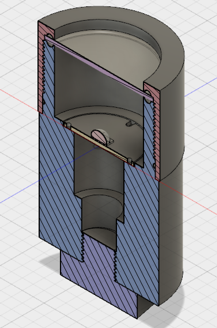
Here's what my design looks like so far with a 32mm MCPCB and a spot for a 26mm driver. The bottom nut will have a cable gland leading to an external battery pack. Reflector is TBD. Body is Aluminium

wmSWd5m.png


Thanks all,
Mike
 

DIWdiver

Flashlight Enthusiast
Joined
Jan 27, 2010
Messages
2,725
Location
Connecticut, USA
Hi Mike, and welcome to the forum!

I'm a diver myself and have made and modified a few dive lights over the years, and have designed a number of LED drivers for various purposes, including dive lights.

You are correct that in general it's more efficient to run higher voltage and lower current, but it isn't always that simple....

A couple of things first off - that isn't a 12V LED, nor is is a 14.8V battery.

I just pulled down the XHP70 datasheet, and it says 11.6-12.4V at 1.05A, 85C. You are planning to overdrive it, so I had to extrapolate the curve in the data sheet and estimate that you'll be running a bit to quite a bit over 13V at 3A. You probably won't be running much cooler than 85C, which is fine. If you did manage to keep it cooler than 85C, that would increase the voltage a bit more.

LiCo and LiPo batteries have a significant voltage change over discharge. 4S batteries do have a 'nominal' 14.8V output, but straight off the charger, it's around 16.8, dropping rapidly to 16.0 under load, then more gradually to somewhere between 10 and 12V depending on what you want to call end of discharge. The 'end of discharge voltage' is somewhat arbitrary, and up to the designer/user. 10V (2.5V/cell) is kind of a minimum. Below this the cells start to degrade rapidly. 10.8V (2.7V/cell) would give better cycle life, and is a more common choice. 12V (3V/cell) would give you even better cycle life, but slightly less capacity. Except at very heavy loads, the difference in capacity between 3.0V/cell and 2.5V/cell is pretty small.

Now the landscape is a bit different. Do you really want to drive a 13+ volt LED with a 12-16V battery, and a buck regulator? Maybe, maybe not.

But before you decide, it gets even worse than that. In general, buck regulators are more efficient with low overhead. Overhead is the difference between input and output voltages. Buck regulators can operate at 97-99% efficiency with overhead as low as a few tenths of a volt, or even less. But ... many buck regulators will not give you full output current unless the overhead is a volt or even more. I've seen them higher than 2V.

So what does all this mean?

If you connect your 14.8V battery to your 12V LED with a buck regulator, you should expect full output and high efficiency with a fully charged battery. At some point during discharge, the output level and efficiency will begin to diminish, and will continue to diminish until something shuts off the light - battery protection, driver, or user. The point at which the output begins to fall, and the efficiency of operation after that, will depend heavily on the driver design.

Contrast this to a design with a 6V LED. There will be LOTS of overhead at all times. There will not necessarily be any diminishing of light output until something (most likely the battery protection circuit) says "that's it, I'm done, lights out'. The driver may or may not warn you that this is about to happen.

So what's the better design? That's for the designer to determine.

Ready to answer lots of questions.

DIWdiver
 

Lenaxia

Newly Enlightened
Joined
Apr 3, 2017
Messages
5
Hi DIWdiver!

Very helpful writeup, thank you! Your 6V arguments are pretty compelling, this light is intended to be a recreational light and as such maximum efficiency takes a back seat to ease of use and design. Based on your information, it definitely seems like 6V will likely be better for me.

I'll bold my questions below to make it easier to parse!


With 6V settled then, it looks like the dedicated XHP70 drivers I've found (mtnmax 26mm and kaidomain 4-18V) cap out at 5A, I can live with that unless you have any recommendations for 6A+ drivers. I'm assuming with that, the XHP70, MTNMAX and a LiPo 4s protected pack it should be largely plug and play right?

I was planning on buying a pre-wrapped or custom battery pack for my first canister with built in BPS, is it safe to assume that if a pack has a BPS board that over-disarcharging will near impossible?


My next set of questions then are about optics as I've been having trouble finding or figuring out which reflector to use. How much does the LED itself impact the beam angle coming out of any given reflector? Or better yet, can you explain how you pick/find your reflectors to get the desired 6-10 degree beam angle?

Do you have any experience with collimators? If used properly they would give an almost 0 degree beam if desired (could play with focal length). I found some interesting ones here: https://www.thorlabs.com/newgrouppage9.cfm?objectgroup_id=3835, maybe for my next project using a CXB3070 (106W!)
 

DIWdiver

Flashlight Enthusiast
Joined
Jan 27, 2010
Messages
2,725
Location
Connecticut, USA
Buck-boost regulators are great in certain applications. Unfortunately, they have inherently the lowest efficiency of the switchers, and they take more to build. That said, the devil is in the details and a well-made buck-boost is better than a poorly made anything else. If you found a good one, it would certainly be worth considering.

Yes, that combo should be plug and play.

I prefer to think of the BPS as a backup system, not a primary. Also, they generally allow for deeper discharge than is healthy for the cells, especially if you were to leave them in that discharged state for long. I prefer to cut off at 2.7 or even 2.8 V/cell, not the 2.5 that protection systems generally allow. That makes for longer battery life at the expense of only a tiny fraction of the capacity.

For dive lights, I prefer lenses for optics, as they can eliminate the unavoidable spill from a reflector (just think where most of the LED light goes - straight out the front without ever hitting the reflector). Check out my favorite dive light: http://www.candlepowerforums.com/vb/showthread.php?369404-MJ-852-mod-with-XM-L2. This preference goes with my typical diving - enough natural light to find your way around, and not great visibility. In other conditions reflectors and/or wider beams can make more sense.
 

Lenaxia

Newly Enlightened
Joined
Apr 3, 2017
Messages
5
Great! I will investigate Fresnel lenses, I'm a huge fan of optics so I might lean towards an aspherical lens but we'll see.

One last question and I think I'll have enough information to push forward:

So with BPS as a backup, I'm assuming you use the driver as the primary determinant for when to shut down.

So in the case of the MTNMAX buck driver (http://www.mtnelectronics.com/index.php?route=product/product&path=67_115&product_id=690) for a 4S circuit it describes a LVP with a 12V ramp. Would I be reading it correctly to say that once the driver reaches an input of 12V, it will either ramp down or shut down (depending on the design)? This 12V is obviously higher than your suggested 2.7V/cell (2.7*4 = 10.8V), but its the same purpose right?

Okay I lied, I've got a 2nd question:

For all of these nicer buck drivers, what does 50% power actually mean? At 50% does it cut current by 50% (since that's the only regulated output)? That obviously doesn't translate to light emitted so I'm assuming I'd have to dig into the LED specs and find the current that gives 50% flux if I wanted 50% light output, right?
 

DIWdiver

Flashlight Enthusiast
Joined
Jan 27, 2010
Messages
2,725
Location
Connecticut, USA
I could only guess at exactly what "12V ramp" means. I'm sure there's someone around who can answer that, though. If not, call MTN. I hear tech support is excellent.

Typically what is meant by "50%" is half the output current. But there are two ways to achieve that. If you turn it on and off, so that it's only on 50% of the time (this is called PWM dimming), then you get pretty close to half the power and half the light. If instead you actually cut the current in half (analog dimming), then it's a bit different. Since the Vf of the LED drops at lower current, this takes slightly less than half the power (into the LED), and because efficacy is better at lower current, you get slightly MORE than half the light. The tint may also change a little. Depending on the driver, the efficiency may be higher, lower, or nearly the same. So the power into the driver could be half, or slightly more or less.
 

Lenaxia

Newly Enlightened
Joined
Apr 3, 2017
Messages
5
Got a response from them:

Thelight will blink then step down power by approximately half, then the voltagewill recover a bit on the batteries. As it sags down again to the setpoint, it will cut power again, and again, until the light is at its lowestlevel, then the light will shut off.

Also I realized there's a design flaw in my design... It seems a lot of these circular drivers have the negative input on the outer edge of the PCB. Meaning if the driver is sitting below the LED in the diagram above, it will be grounded to the light head case. I'm assuming that's a bad thing but I need that or some other connection to heat sink (MTN says their drivers must be soldered to the pill).

Do you have any suggestions for electrically isolating the driver from the light head while still providing enough thermal sink to avoid damaging the driver?

[edit] Looks like silicone thermal pads may be the way to go. ​https://www.digikey.com/en/product-highlight/b/bergquist/sil-pad-900s
 
Last edited:

DIWdiver

Flashlight Enthusiast
Joined
Jan 27, 2010
Messages
2,725
Location
Connecticut, USA
What's wrong with the light head being grounded? Most lights are built that way. That's why that ring is there.
 

Lenaxia

Newly Enlightened
Joined
Apr 3, 2017
Messages
5
What's wrong with the light head being grounded? Most lights are built that way. That's why that ring is there.

Does that apply to dive lights as well? Based on my knowledge of electronics it shouldn't be a problem but I'm used to designing transistors, not flashlights, so you never know :p The dive lights I do have don't have grounded hosts, the circuit is fully contained inside.
 

DIWdiver

Flashlight Enthusiast
Joined
Jan 27, 2010
Messages
2,725
Location
Connecticut, USA
Every one I've built is that way. The thing that would be bad is if you have different parts at different voltages. Lights that have a head or tail that screws in and out to turn it on and off would be a disaster as a dive light.
 
Top