AJH_CUSTOMS
Newly Enlightened
- Joined
- Dec 20, 2018
- Messages
- 4
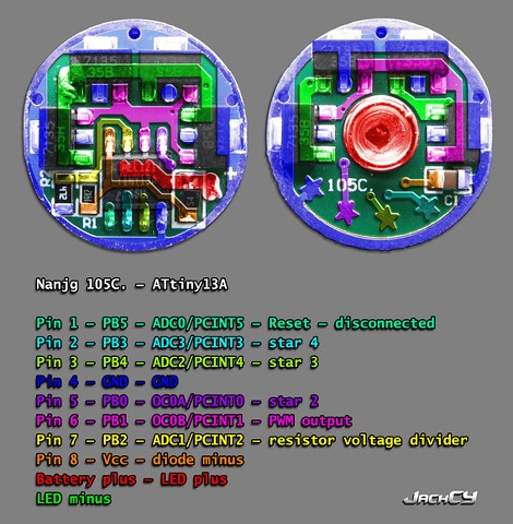
Hey there guys. I am planning on using the ATtiny13 in my driver. My friend is writing the code and is having trouble because the switch to control the mode also controls the on or off states of the flashlight.
Can anyone share a schematic on how the ATtiny13 is typically connected when only using one switch. I'm not a software guy, I have 2 switching regulator designs that i need to control with the ATtiny13. can anyone shed some light on this.. no pun intended..")
Aaron
Can anyone share a schematic on how the ATtiny13 is typically connected when only using one switch. I'm not a software guy, I have 2 switching regulator designs that i need to control with the ATtiny13. can anyone shed some light on this.. no pun intended..
Aaron