Dynamo lights for dummies

Steve K

Flashlight Enthusiast
Joined
Jun 10, 2002
Messages
2,786
Location
Peoria, IL
Re: Automatic switching methods

Should I be concerned that the LT4320 has a minimum input of 9V, given that I am looking to improve low speed performance & have a target of ~5.3V ?.

yeah.... that could be a problem.

how slow do you need/want to go, and how much light do you need at that speed? If you are looking at 5.3v, then you've just got one white LED and a red LED in series, I'm guessing. That's lower than what I've got, with two white LEDs and some paralleled 1.8v red 5mm LEDs in series. My light works down to 3.5mph, albeit dim and flickering. I think you might get by with a bridge rectifier made of schottky diodes.
 

znomit

Enlightened
Joined
Aug 1, 2007
Messages
979
Location
New Zealand
Re: Automatic switching methods

Hmmm, I've been using 1n5822 diodes for their low voltage drop, but looks like 1n5817 might be a better option ( <.3V @ 500mA).
 

Steve K

Flashlight Enthusiast
Joined
Jun 10, 2002
Messages
2,786
Location
Peoria, IL
Re: Automatic switching methods

hmmm indeed! Looking at On Semi's datasheets, they spec Vf= 0.370 @ 1A for the 1N5820, and 0.45v @ 1A for the 1N5817. Is that due to the lower current density in the diode rated for 3A instead of 1A? I think you could have chosen the 1N5820 and gotten a lower Vf, but the bigger diode seems like the right choice when you want the lowest Vf.

For some folks, the smaller diode package might be worth the extra 0.08v of Vf.

Whose datasheet had data for 0.5A? It seems like datasheets have gotten smaller and smaller over the years.
 

find_bruce

Newly Enlightened
Joined
May 5, 2011
Messages
84
Re: Dynamo lights for injineers

Is it time to change the thread title yet?
I seem to have lost sight of one of my design goals - the KISS principle.

how slow do you need/want to go, and how much light do you need at that speed? If you are looking at 5.3v, then you've just got one white LED and a red LED in series, I'm guessing. That's lower than what I've got, with two white LEDs and some paralleled 1.8v red 5mm LEDs in series. My light works down to 3.5mph, albeit dim and flickering. I think you might get by with a bridge rectifier made of schottky diodes.
Ride harder is always an option :D At the moment I am annoyed by a slow strobe from the LED without the super cap at ~10 km/h (6.25 mph). The 5.3V was a figure I plucked from 2 x XM-Ls at 0.15A. I can probably get by with a schottky bridge rectifier, esp at the low Vf found by Znomit, just by switching the two rear red leds out at low speed, because (1) the red standlight is bright & (2) I have a li-ion powered red XP-E on my helmet.


Steve K

Flashlight Enthusiast
Joined
Jun 10, 2002
Messages
2,786
Location
Peoria, IL
Re: Dynamo lights for injineers

I'm not sure that KISS is the highest priority. Reliability, for me, is the priority. Complexity is okay as long as it is proven out, and is well constructed. Goodness knows we have plenty of complex electronics in our lives, and the hardware is normally pretty reliable. The software, however....
 

find_bruce

Newly Enlightened
Joined
May 5, 2011
Messages
84
A minor update & a thought

I have made a minor update to my lights - I regularly ride with my little boy on a weehoo, using a red flashlight as a taillight. I have been thinking about how to add an extra tail light into my dynamo set-up without stuffing up the standlight circuit.

It occurred to me that ~0.5A is more than enough for 1 red led & ~0.25A is still adequate, so I grafted a plug into the wiring to add the extra red led in parallel with the first. Simple enough to plug the light in when I connect the weehoo, standlight works for both lights, all is good. Disconnect the weehoo & lights work as before.

As thoughts often lead onto other thoughts, I am now wondering whether this is a way to have a flashing taillight without flashing the front lights - ie have the lights physically spaced apart & set up the timing so there is a brief overlap when both are on, or more importantly, no time when neither light is on.
 

Steve K

Flashlight Enthusiast
Joined
Jun 10, 2002
Messages
2,786
Location
Peoria, IL
Re: A minor update & a thought

..

As thoughts often lead onto other thoughts, I am now wondering whether this is a way to have a flashing taillight without flashing the front lights - ie have the lights physically spaced apart & set up the timing so there is a brief overlap when both are on, or more importantly, no time when neither light is on.

do you have a schematic for the lighting system that you are interested in modifying?
 

find_bruce

Newly Enlightened
Joined
May 5, 2011
Messages
84
Re: A minor update & a thought

Sorry Steve, should have remembered things make more sense with a schematic. IIRC this is what I have at the moment
5CaIgNXfCwYpGawozlFSimvR2Guk3ipi3-o8tBi8FdY=w1005-h565-no


What I am wanting to do is alternate LED4 and LED5 without flashing LED1-3.
 

Steve K

Flashlight Enthusiast
Joined
Jun 10, 2002
Messages
2,786
Location
Peoria, IL
Re: A minor update & a thought

Something could be made using a LMC555 oscillator circuit. It will run down to 1.5v, according to the datasheet:
http://www.ti.com/lit/ds/symlink/lmc555.pdf
The LMC555 would have to be powered by the same power that LED4 & 5 are powered by now.

a couple of transistors and probably a few resistors might be needed to do the switching of the LED current.
The hardest part might be ensuring that the switching between the two works smoothly without any period where both are off.
The simplest method might be to use the LMC555 to drive a npn transistor that is wired between LED4's cathode and ground.
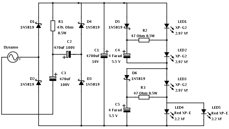
LED5 would have a silicon diode (such as a 1N4001 or other generic diode that can handle at least 0.5A) between its cathode and ground.
When the npn transistor is on, the current would go through LED4.
When the npn is off, the current would go through LED5 and the diode because there is nowhere else to go.

When LED5 is conducting, there is about 0.5v more voltage drop in the whole circuit compared to when LED4 and the npn are conducting. This will reduce the current very slightly. I can't imagine that it would be visible, so it should be acceptable.
 
Top