Poorman Mutli-Lux setup method

Mettee

Enlightened
Joined
Aug 5, 2008
Messages
678
Location
Arizona
the very first light that I built used a three board set up, one multi mode and two slave 7135 boards with one chip removed from each slave.

The new 17 mode can be made to 1400ma and if you leave the chips on the slave boards that is another 1400x2. 4.2A.

I am planning on trying the same thing you are thinking, I am sure it will work somewhat but the battery may have trouble keeping up with current unless like you said you use nimh.
 

vestureofblood

Flashlight Enthusiast
Joined
Jun 19, 2008
Messages
3,211
Location
Missouri
Hi Download,

I just wanted to double check and make sure my thinking is correct on a wire path.

If I wired 3 MCE emitters in this pattern DD, would all of the dies get equal current?
 

TorchBoy

Flashlight Enthusiast
Joined
Jan 15, 2007
Messages
4,486
Location
New Zealand
Re: Poorman Multi-Lux setup method

If I wired 3 MCE emitters in this pattern DD, would all of the dies get equal current?
No, you've got two paralleled LEDs in series with a third. The two in parallel would share the current that all goes through the other LED.
 

vestureofblood

Flashlight Enthusiast
Joined
Jun 19, 2008
Messages
3,211
Location
Missouri
Hmmm, I sort of thought that might be to good to be true. What you are saying is that if the first emitter was getting 4 amps the next two would get only 2 amp each?

Guess I better stick with what I have. Right now I did basically the same thing but I split the second emitter in 1/2 giving 6 die on each side. This works fine but its a lot of very tiny connections using a thing gauge wire. For a minute I thought I came up with a way I could use some much thicker wire.
 

download

Flashlight Enthusiast
Joined
Jun 26, 2005
Messages
1,630
Location
Sol 3
Or you could wire like this, but some MCE Volt-in is quite low.
May :poof: within 0.5 sec.

3xMCEdirect-drive.jpg
 
Last edited:

download

Flashlight Enthusiast
Joined
Jun 26, 2005
Messages
1,630
Location
Sol 3
It may affect the mode changing if letting small current to the driver.
Because it stay alway ON. :shrug:
 

TorchBoy

Flashlight Enthusiast
Joined
Jan 15, 2007
Messages
4,486
Location
New Zealand
If the switch isn't feeding power to the Vdd pin the driver wouldn't be on, so the second LED (counting from battery positive) wouldn't be on, so the LED series wouldn't be on. The problem is that you'd need to drop the voltage fed to that pin, for which you could use one of the LEDs.

In other words, shift the Mag switch to the blue wire just above the words "Driver out LED(+)" and it would work fine but with next to no current on the switch.
 

download

Flashlight Enthusiast
Joined
Jun 26, 2005
Messages
1,630
Location
Sol 3
Next to the Output to LED+ is a diode, it is for the reverse polarity protection. :)
 

vestureofblood

Flashlight Enthusiast
Joined
Jun 19, 2008
Messages
3,211
Location
Missouri
Thanks, that is what I suspected. I wanted to use one of these boards as a single mode with the controller and extra chips removed, but still enable the rev poll protection.
 

SmurfTacular

Enlightened
Joined
Feb 16, 2010
Messages
704
Location
Orange County, CA
Actual wiring diagram for ref.

MC-Ewiring1-1.jpg


That is a really useful diagram. But does it have to use an MCE??? What if I put in a P7 instead? Because I have about twenty P7's on hand, and about five of your 7135 drivers, and I want to use them. Is there any way of driving a single P7 with one or two of your 7135 drivers?
 

download

Flashlight Enthusiast
Joined
Jun 26, 2005
Messages
1,630
Location
Sol 3
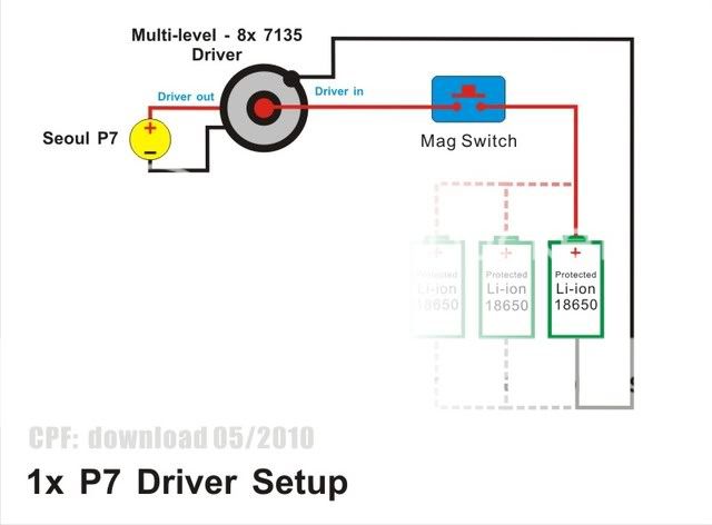
Here is the 1xP7 setting. 1x Driver to 1x LED with 1 battery (or parallel more), Max.2.8A to LED.
Parallel more battery will extend the run-time.
WirediagramP7x1.jpg
 

SmurfTacular

Enlightened
Joined
Feb 16, 2010
Messages
704
Location
Orange County, CA
Re: Poorman Mutli-LED setup method

I found some interesting setup method to use the cheap driver board like 7135.
It can be used multi Seoul P7 or Cree,
like 2x li-ion to 2x LED or 3x li-ion to 3x LED.
It works quite well for me. Hope it helps you too.

3xP7DriverSetupb.jpg

Each P7 can get 2.8A !!!
]

if you wired that driver with the 5 mode setting, do all the LED's change when you change modes? Or does just one change?
 

owent

Newly Enlightened
Joined
May 28, 2010
Messages
3
Location
Lafayette, USA
Actual wiring diagram for ref.

MC-Ewiring1-1.jpg
Hi all i am new to the forum and to building LED lights, looking to build a headlamp using this set up
help.gif
would a shining beam driver sku 1217 be good to run this set up? how would i wire it so as not to exceed the 6v max for this driver would be using the two 18650 bat shown.
like i said new to this and it is still all a little over my head.
Thanks
 

TorchBoy

Flashlight Enthusiast
Joined
Jan 15, 2007
Messages
4,486
Location
New Zealand
would a shining beam driver sku 1217 be good to run this set up? how would i wire it so as not to exceed the 6v max for this driver would be using the two 18650 bat shown.
No, that diagram appears to be wrong - you really want a 1.4 A driver for that configuration. The way it's arranged two dice of the LED drop (almost) half the voltage before the driver and the two dice that are controlled by the driver, so the full voltage of the two cells isn't seen by the driver.

You could use that driver if you wired all 4 dice in the LED in parallel and used just one Li-ion cell - see the diagram in post 236 above.
 
Top