reed activated mosfet switch diagram

uk_caver

Flashlight Enthusiast
Joined
Feb 9, 2007
Messages
1,408
Location
Central UK
I'm just wondering (not questioning anybody), if the switching is only going to be around an amp, what would be wrong with using a physically much smaller FET.
Is it purely a case of having a lower 'on' resistance (a few milliohms rather than a few tens of milliohms), or are there other factors that are important, like a larger FET being able to cope with being partially turned on in a fault condition?

On the face of it, even some very small FETs can handle decent currents when fully on, and can have very low thereshold voltages and gate charges.

Really I'm trying to get a handle on whether there are some Golden Rules about having very big safety margins, or whether people are being more focussed on the particular application, and reasoning that if there's enough space, there's no great reason not to use a larger FET, or that a TO220 is simpler to deal with than a tiny surface-mount component, etc?
 

VidPro

Flashlight Enthusiast
Joined
Apr 7, 2004
Messages
5,441
Location
Lost In Space
Some people, when told publicly that they're wrong, ask questions to learn more - some people just lose it.

The latter certainly shouldn't post information -and VidPro certainly fits in that second category.

and exactally what was wrong with using a SPDT? which was my main point? did i miss something , Will it Work Or not? or are you having to much fun :naughty: herassing me about my methods?
 

SemiMan

Banned
Joined
Jan 13, 2005
Messages
3,899
I'm just wondering (not questioning anybody), if the switching is only going to be around an amp, what would be wrong with using a physically much smaller FET.
Is it purely a case of having a lower 'on' resistance (a few milliohms rather than a few tens of milliohms), or are there other factors that are important, like a larger FET being able to cope with being partially turned on in a fault condition?

On the face of it, even some very small FETs can handle decent currents when fully on, and can have very low thereshold voltages and gate charges.

Really I'm trying to get a handle on whether there are some Golden Rules about having very big safety margins, or whether people are being more focussed on the particular application, and reasoning that if there's enough space, there's no great reason not to use a larger FET, or that a TO220 is simpler to deal with than a tiny surface-mount component, etc?

Sorry I should have explained that better. I picked the TO-220 as it a large enough tab to provide some inherent heat sinking without needing to heat sink it to anything else. That provide some margin when/if the part is not fully turned on. It also has leads which are much easier to work with for such a situation.

Many SMT parts have even lower on resistance as the limitation is starting to be the package when you get to very low on resistances. That said, they are not the easiest to solder wires to in a reliable robust way. DPAK/D2PAK being useful exceptions and still in the size range of a TO-220. If I was putting a part down on a board, I would not go TO-220 unless I was trying to heat sink into a case of similar. For these currents, little SOT-23's can be found that would be good enough, but without some copper on a board, they will overheat if they are not fully turned on.

I also did not get the impression that archer was that concerned about price in the short term.

Semiman
 

SemiMan

Banned
Joined
Jan 13, 2005
Messages
3,899
and exactally what was wrong with using a SPDT? which was my main point? did i miss something , Will it Work Or not? or are you having to much fun :naughty: herassing me about my methods?

It would work quite well actually and you can buy them from Digikey in small quantities for about $3.00 - $3.50. That said, the improvement over using a pull down will be minimal.

Semiman
 

archer6817j

Enlightened
Joined
Aug 9, 2010
Messages
830
Location
Mountain View, CA
Thanks for the help so far!

It's true, I'm not that concerned with price if we are talking about a few dollars. I looked at the digikey links and they seem to be a smaller package size as the NTE (around 1/2 inch) but the TO-220 is listed as 6mm...which is about 1/4". How hot would these get in practice? I'm hoping to not heat sink them at all in terms of ease of installation.

The other side of that would be, given the fets in question (my NTE and the two from digikey) how many amps can I run without heat sinking? Eventually I'm going to try an MCE, P7, and SST50/90 which of course all have very different current requirements.

What might be interesting (if it makes any sense) is to come up with a little table of FET part numbers that are tied to specific LED packages (or current draw) so you can just look at the LED you want to use and see the best FET for that application. Feasible? In the end I'd like to have something to use myself but also generate a set of data that will be helpful to others working with reed/fet setups.

Oh and the resistors I have are actually 10k...so I should be good on that one right? I'm also not worried about the minimal drain. Since this is for a dive light application the batteries should be charged before use so I don't really care about shelf life as long as it won't suck the batteries dry and cause a fire.
 
Last edited:

DIWdiver

Flashlight Enthusiast
Joined
Jan 27, 2010
Messages
2,725
Location
Connecticut, USA
I'd like to amplify what Semiman said. The big TO-220 is massively overkill at 1A. But it's easy for a beginner to work with, readily available, and not expensive, so where's the harm? The DPAK, IPAK, and SOT-223 sizes are much smaller and not too bad to work with, but anything smaller is very hard to reliably solder wires to. If you have a PCB, the SOT-23 size is pretty easy, but smaller ones get pretty tough to do by hand.

When you get into those really small packages, or if you use higher currents in the bigger packages, you have to be careful. It's really easy to read the data sheet, see that a part can handle 10A and dissipate 1.5W, only to find that the part fails at 6A, 1/2W in your design.

The reason for this is that the power and current ratings of most FETs are WILDLY optimistic. Often they assume an infinite heatsink at 25 degrees, which simply isn't practical. Sometimes they even claim currents that the die can support but the package pins cannot. This may well be the cause of the crappy designs that VidPro refers to.

In order to properly engineer a FET solution without resorting to overkill (and thus increasing the cost of your product), you have to have an understanding of thermodynamics, material properties, the environment a product will be exposed to, how to read data sheets and interpret (and sometimes interpolate) the data, as well as how reliability is affected by pushing or derating various limits. Whew! It's no wonder we sometimes resort to overkill.

That said, I'm sure that today there are parts in the IPAK or SOT-223 packages that would handle the OP's project quite well. If anyone needs a recommendation for one, I'll be happy to provide one.

D
 

DIWdiver

Flashlight Enthusiast
Joined
Jan 27, 2010
Messages
2,725
Location
Connecticut, USA
Thanks for the help so far!

It's true, I'm not that concerned with price if we are talking about a few dollars. I looked at the digikey links and they seem to be about the same package size as the NTE...something around 1/4 inch. How hot would these get in practice? I'm hoping to not heat sink them at all in terms of ease of installation.

The other side of that would be, given the fets in question (my NTE and the two from digikey) how many amps can I run without heat sinking? Eventually I'm going to try an MCE, P7, and SST50/90 which of course all have very different current requirements.

What might be interesting (if it makes any sense) is to come up with a little table of FET part numbers that are tied to specific LED packages (or current draw) so you can just look at the LED you want to use and see the best FET for that application. Feasible? In the end I'd like to have something to use myself but also generate a set of data that will be helpful to others working with reed/fet setups.

Oh and the resistors I have are actually 10k...so I should be good on that one right? I'm also not worried about the minimal drain. Since this is for a dive light application the batteries should be charged before use so I don't really care about shelf life as long as it won't suck the batteries dry and cause a fire.

In practice, it's pretty safe to dissipate 1.5W in the TO-220 without heatsink. At that level it would be very hot to the touch, but would not burn you quickly.

What does that mean for current?
P = I^2 * R
Where P is power in watts, I is current in amps, and R is resistance in ohms.

If you know the resistance of the FET when turned on you can easily calculate the current,
I = SQRT(P/R).

I would probably count on the resistance being 1.5-2 times the lowest resistance quoted in the data sheet, unless I could read and understand the datasheet well enough to get a better idea of what to expect in my application.

For the NTE2389, Rds(on) is specified as 0.045 ohms. I would plan on 0.067 to 0.090 ohms.

I = SQRT(1.5/0.067) = 4.7A
or
I = SQRT(1.5/0.090) = 4.1A

I would probably use the lower value for a 2-cell light where the gate voltage is a bit low, and the higher one for a 3-cell light where the gate voltage is higher.

And yes, your 10K resistor is fine so long as you can afford the additional power drain. It won't affect shelf life, because the resistor only draws current when the light is on.

D
 

uk_caver

Flashlight Enthusiast
Joined
Feb 9, 2007
Messages
1,408
Location
Central UK
Digressing somewhat, if someone was worried about drainage current when on, what limits the upper value a pull-down resistor could take - is it the possibility of the FET being turned on (or being prevented from turning off) by leakage currents, or is it simply to avoid having the FET transiently passing large currents in linear mode for a meaningful time (or having the load slowly powered down)?
 

DIWdiver

Flashlight Enthusiast
Joined
Jan 27, 2010
Messages
2,725
Location
Connecticut, USA
Digressing somewhat, if someone was worried about drainage current when on, what limits the upper value a pull-down resistor could take - is it the possibility of the FET being turned on (or being prevented from turning off) by leakage currents, or is it simply to avoid having the FET transiently passing large currents in linear mode for a meaningful time (or having the load slowly powered down)?

You pretty much nailed it. In some applications, there's also the possibility of noise getting picked up and turning on the FET when you don't want it to. But in a light that's probably not an issue.
 

SemiMan

Banned
Joined
Jan 13, 2005
Messages
3,899
Thanks for the help so far!

It's true, I'm not that concerned with price if we are talking about a few dollars. I looked at the digikey links and they seem to be a smaller package size as the NTE (around 1/2 inch) but the TO-220 is listed as 6mm...which is about 1/4". How hot would these get in practice? I'm hoping to not heat sink them at all in terms of ease of installation.

.

Giving you are putting it inside of the flashlight where convection is going to be limited, I would not go much beyond 0.5W but since the goal is to put power into the LED and not the FET, go with as low of resistance as is practical (cost, etc.). Also keep in mind that you have to look at max on resistance which is often specified at room temp and then adjust for maximum temperature. Hence for this reason keeping the FET cool by keeping the on resistance low makes a lot of sense.

For the ones I specified, even on a single cell, I would estimate the RDSon at 0.01 ohms or so worst case assuming a gate voltage of 3.7. Let's call it 0.015 just to be careful. That gives you about 6 amps, but I would keep it well under this to ensure the part stays cools and the RDSon stays low. Keep in mind you can parallel them to reduce the on resistance.

Semiman
 

archer6817j

Enlightened
Joined
Aug 9, 2010
Messages
830
Location
Mountain View, CA
UPDATE: do not use the NTE2839 MOSFET as indicated on my drawing :poof:

Especially if you don't know anything about electronics...like me. I had this in a 2s 18650 light (P7) that draws about 2.8 amps. Fortunately I noticed that the MOSFET got 'really' hot before it set anything on fire. It was melting wires that it was touching. I got lucky and opened the light, it was working intermittently, and there was smoke inside from melting insulation.

You are going to want to use this MOSFET, which was recommended by CPF member, SemiMan: http://search.digikey.com/scripts/Dk...=497-9093-5-ND

I installed in place of the NTE2839 and it barely gets warm to the touch. Awesome!
 

MikeAusC

Enlightened
Joined
Jul 8, 2010
Messages
995
Location
Sydney, Australia
The NTE2389 seems to have a typical gate threshold of 3V, but with min and max of 2V1 and 4V.
Also, the threshold voltage is where the FET starts to turn on, not where it's completely on.

Depending on luck with the individual FET, it is possible that the circuit might not work.

Words of Wisdom !!!

Junction transistors need less than one volt to turn on fully, but do draw some current.

FETs draw zero current for a DC switch, but only certain ones will switch on fully using the 3.0 volts from a single LiIon cell at the end of its discharge. If it doesn't switch on fully, it has a voltage drop which produces heat in the FET.
 

fyrstormer

Banned
Joined
Jul 24, 2009
Messages
6,617
Location
Maryland, Near DC, USA
Why worry about 1 milliamp being used by the resistor? That's easy: because it's wasted power. The power being used to drive the LED is not wasted because it's doing useful work -- or at least, the power that is wasted by the LED producing heat is beyond the control of the designer, but the power being wasted by the resistor is within the control of the designer, so it's a valid target for improvement.

Don't ask "why try to make it work better?", ask "why not try to make it work better?" "Why not?" is the question that drives progress.
 

darkside501st

Newly Enlightened
Joined
Jul 31, 2012
Messages
2
Why worry about 1 milliamp being used by the resistor? That's easy: because it's wasted power. The power being used to drive the LED is not wasted because it's doing useful work -- or at least, the power that is wasted by the LED producing heat is beyond the control of the designer, but the power being wasted by the resistor is within the control of the designer, so it's a valid target for improvement.

Don't ask "why try to make it work better?", ask "why not try to make it work better?" "Why not?" is the question that drives progress.

Wow, I have been looking for a solution to my problem for three days. While this is an older thread and you brought it back from the dead I might not have seen it otherwise. I just wanted to say thanks to everyone that posted all the helpful information here.

I am working on a project using a fade-in/fade-out circuit for LEDs. I am building some repulsor props for a friend of mine who has an Iron Man costume. He wanted to use some reed switches to activate the LEDs but when I tried one it got stuck in the closed position. I am not sure what caused it. The rating on the switch is 500mA. My circuit draws about 50mA so I don't think that it was excessive current. Anyways, I thought that isolating the switch from the circuit through a relay was the answer. I was looking at some relay circuits when I came across this forum/thread. I am just a beginner working with circuits and components. I would not have thought about using a Mosfet instead of a relay. So thanks again for all the help given in this thread. I am going to start some experiments now. :grin2:

Well, I did some more experiments and unfortunately using a mosfet as a switch won't work with my circuit. My circuit needs to maintain a connection to the ground in order for the capacitor to drain through the LEDs and produce the fade-out effect. I am not sure if it is possible to connect the mosfet in this manner.

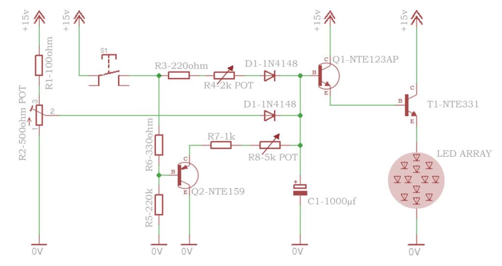
This is my circuit in case anyone wants to take a look over it and tell me if they see a way around this issue.


My power source for this circuit is 4 AAA batteries at 6v (6.5v w/fresh batteries). I am using a BC548 at Q1 and a BC327 at Q2. I am also using a different power transistor, 2N5296, at T1 but I don't even know if I need that. The max current for the LEDs will be 240mA - 720mA max depending on the LEDs I use.

It was mentioned earlier in this thread that a DPST reed switch would be a good idea but I don't quite understand why or what the purpose of that would be. I would love for someone to go over that with me.

Then, I am just wondering if there is a way to use a mosfet in this circuit or if there is something else I need to do to protect the reed switch from being damaged. It is possible that it was a defective switch but I am afraid of messing up another one.

My friend already has SPST reed switches and I have to activate this LED circuit and a sound module at the same time. I was thinking of looking for a DPST or DPDT relay to activate both at the same time. Otherwise I would have to use two mosfets, right? The sound module will be running off of the same power source; but I am not connecting power to it, I am closing the switch to activate the sounds. I know a relay would do that but I don't know about the mosfet. It seems that the power across the switch has to be at a certain voltage for the IC to play the sound. I can't just send power from the battery to the other side of the switch. I have to send power from one side of the switch to the other. Would the mosfet 'corrupt' that power/voltage signal to play the sound?

One thing I did find while looking at how to protect the reed switch was that most companies selling them recommend using a relay and on DC circuits to wire a diode (1N4004) parallel with the relay. I don't understand the mechanics of what is happening there or why the resistor/mosfet setup in this thread works without it.

Any help would very much be appreciated. Thanks, Mike
 
Last edited:

darkside501st

Newly Enlightened
Joined
Jul 31, 2012
Messages
2
Ok so it turned out that using the Diode 1N4004 was all that was needed. I hooked it up in parallel with the load with the cathode connected just after the switch and the anode connected just after R5 on the negative rail. It worked like a charm... I tested it for several minutes without any issues.
 

uk_caver

Flashlight Enthusiast
Joined
Feb 9, 2007
Messages
1,408
Location
Central UK
The gate threshold voltage for that FET (2V0 to 4V0) is too high for reliable switching from a 1C setup.

What kind of load current are you switching?
 
Top