Standlight circuits (Will this circuit work?)

Bandgap

Enlightened
Joined
Aug 14, 2002
Messages
284
Location
London
Re: Will this circuit work?

....If you want an even better standlight use two gold caps in series in place of the smoothing capacitor.....If you do this you should use some voltage balancing resistors (10K ohms or so) across each goldcap to make sure the caps discharge fully overnight, this will prevent the caps from charging unevenly.

Nice to hear some experience. I have only ever used supercaps with a rear light.
How about connecting the mid-point of the caps to the midpoint of the leds and not needing the resistors.

And isomax, not all GoldCaps are the same.
Some have high internal impedance so charge and discharge slowly - 'uA' types
others have low internal impedance so charge and discharge quickly - 'A' types
and there are 'mA' types in the middle
see www.panasonic.com/industrial/components/capacitive/cap_gold.htm
It is mostly the same for other super-cap brands.

Does anyone want 4 (or 5) component circuit that will charge your super cap quickly, and control the current into the bottom led? It will waste 5mA (1%)
If you stay at 20mA in standby, you will get a dim light, but it will be last for a predictable and useful time.
I would draw it and scan it now, but I can't remember how to post pictures here.

Steve
 
Last edited:

Bandgap

Enlightened
Joined
Aug 14, 2002
Messages
284
Location
London
Re: Will this circuit work?

... I'm tempted to track down a breadboard from one of my friends and prototype it to see if the bottle dynamo can power both LEDs at a reasonable speed

How about soldering the components to the pins of the supercap and taping them to the outside of it.
Would proably last for years in a plastic bag!

It will work fine with a bottle dynamo.

Good luck

Steve
 

syc

Newly Enlightened
Joined
Jun 10, 2008
Messages
155
Re: Will this circuit work?

Does anyone want 4 (or 5) component circuit that will charge your super cap quickly, and control the current into the bottom led? It will waste 5mA (1%)
If you stay at 20mA in standby, you will get a dim light, but it will be last for a predictable and useful time.
I would draw it and scan it now, but I can't remember how to post pictures here.

I would be interested, since I haven't seen many circuits around for standlights which don't seem to involve a lot of components. If you don't have a place to host your circuit image and link to it, I can upload it to my flickr account and link to it for you in this thread.

Steve (seems to be a Steve-fest in this thread!)
 

hopkins

Enlightened
Joined
Nov 15, 2007
Messages
906
Location
California
Re: Will this circuit work?

Always liked generators on bikes except when stopped. Then the cars can't see
you! I'd have to see some beam shots of the Cree being driven by the supercap
at 1sec,15seconds, 60seconds to believe it'd put out enough to keep a driver
from left turning in front of you just as you started across the intersection.

Going from a stop to 1-2mph you're in the middle of the turn area just then and not generating a lot of light at that low speed? My idea here drives one Cree
from a battery while stopped so you can be seen easier.
bikelightcircuit.jpg
 

StevelKnievel

Newly Enlightened
Joined
Oct 13, 2007
Messages
114
Re: Will this circuit work?

Here's a couple shots of one of my bigger dyno lights. Not beamshots exactly, but it's something. I've actually been wanting to take some shots facing the bike in timed intervals to see just how fast the standlight dims and at what point it is to dim to be safe.

This light has 6 Q5s that are running off of 4 1.5F 5.5v supercaps in series. When it's fully charged it gives enough light see and be seen. This picture was taken after the light was charged by riding around for a minute or so and then disconnected from the bike. By the time I took the pic the standlight had been on for maybe 30 seconds to a minute. Just using my eyes to judge it stays roughly this bright for about 3 minutes before it starts to get noticeably dimmer. After 7 to 8 minutes the light is pretty dim, but still visible from a good distance. 15 minutes and it's just barely glowing.

IMG_3523.jpg


IMG_3520.jpg


IMG_3521.jpg
 

syc

Newly Enlightened
Joined
Jun 10, 2008
Messages
155
Re: Will this circuit work?

This picture was taken after the light was charged by riding around for a minute or so and then disconnected from the bike. By the time I took the pic the standlight had been on for maybe 30 seconds to a minute. Just using my eyes to judge it stays roughly this bright for about 3 minutes before it starts to get noticeably dimmer. After 7 to 8 minutes the light is pretty dim, but still visible from a good distance.

That's good to know! I won't be using this particular light in remote areas, its just for a commuter for around town and back and forth from work. Given how many led's you have versus the supercaps, I think 1F or 1.5F for a single Cree should be fine.
By the way, that's a really nice light! I remember coming across it in the archives and trying to track down some more info on it, such as a component list and circuit diagram. Can I ask what supercaps you used and the ESR? The 5.5V 1.5F supercaps I found all seem to be about 30 ohms.

Now, if only DX would stop pushing the shipdate of my order further and further into the future. Hopefully I'll get the parts before the winter commute truly kicks in.

isomax said:
Hi, sorry for my very bad english, i am spanish....

Thanks for the diagram and the design suggestions. I am not particularly good at soldering, so I would rather go with a design that has fewer components, and I suspect that using power LEDs as the rectifier diodes would result in a lot more noticeable flickering.

frontranger said:
Not to rain on your parade, syc, but have you considered just mounting a flashlight on your bars? To make a repair in the dark, you need a light source that isn't dynamo-powered. And if you're carrying one of those around anyway, why not use it as a standlight? With this reasoning in mind, I ditched the standlight idea and augment my dynamo headlamp with an L2D.

This will be used to commute in town, and its rarely more than 2 or 3 blocks to a good streetlight. That being said, I usually carry a Luxeon III flashlight with me for emergencies, though I'd rather not go through the hassle of mounting and unmounting it all the time.

MyAl said:
Now that i take another more close look at this circuit i see
that there could be a better way to run the lower LED....
Thanks for the design tips, but the design is starting to go beyond my meager grasp of electronics! This is my first light, and I'd like to keep it as simple as possible as a learning exercise, that will also turn out to be really useful for my commutes. At this point, keeping the design simple is likely to help me avoid some error in the execution.
 

hopkins

Enlightened
Joined
Nov 15, 2007
Messages
906
Location
California
Re: Will this circuit work?

Hi Stevel - good demo pics. That should do the job for seeing and being seen.
Wonder how much drag the generator (alternator?) makes when riding?
At least one lower gear for flatland spinning when its on for night rides?
All those Leds got to draw a good bit of current.

Cheers
hopkins
 

StevelKnievel

Newly Enlightened
Joined
Oct 13, 2007
Messages
114
Re: Will this circuit work?

It uses Martin's (pilom.com) manually switched voltage doubler/full wave rectifier setup. On the voltage doubler setting the light should be consuming around 6-7 watts and the full wave rectifier setting should be taking around 12 watts, but full wave isn't really necessary and it doesn't come up to power until over 20 mph. The dude who owns this light has it on his 29" singlespeed mountain bike with a Schmidt dynamo hub and he still hauls a$$! (He was super fast to begin with.) He says he doesn't notice the drag, but he does notice the heavier front wheel compared to a regular hub.
 

MrAl

Flashlight Enthusiast
Joined
Sep 9, 2001
Messages
3,144
Location
New Jersey
Re: Will this circuit work?

Thanks for the design tips, but the design is starting to go beyond my meager grasp of electronics! This is my first light, and I'd like to keep it as simple as possible as a learning exercise, that will also turn out to be really useful for my commutes. At this point, keeping the design simple is likely to help me avoid some error in the execution.

Ok, no problem. If you decide later on to improve the design let me know.
Be sure to include a diagram of the circuit too.
Good luck with it...
 

Calina

Enlightened
Joined
Jul 26, 2006
Messages
955
Location
Longueuil, Québec
Re: Will this circuit work?

Quote:
Originally Posted by Bandgap
Does anyone want 4 (or 5) component circuit that will charge your super cap quickly, and control the current into the bottom led? It will waste 5mA (1%)
If you stay at 20mA in standby, you will get a dim light, but it will be last for a predictable and useful time.
I would draw it and scan it now, but I can't remember how to post pictures here.


I would be interested, since I haven't seen many circuits around for standlights which don't seem to involve a lot of components. If you don't have a place to host your circuit image and link to it, I can upload it to my flickr account and link to it for you in this thread.

Steve (seems to be a Steve-fest in this thread!)

That would be great; if not for the benefit of the O.P., at least for the benefit of other members.
 

znomit

Enlightened
Joined
Aug 1, 2007
Messages
979
Location
New Zealand
Re: Will this circuit work?

Great thread here.
I've just built up a 5 led bikelight with a 1F 5.5V supercap across one led.
I'm using Martins circuit 10 which has served me well in the past.

I just wanted enough light for traffic light stops, seems to work well enough on the bench. The standlight led is on an oval polymer optic and the rest are on a cutter narrow quad.

I did wonder about putting all 5 on super caps but was a little worried about lag with the capacitors charging up. Coming over some hills and going from 7 to 50kph quickly I don't want to wait for my lights to catch up. SteveK what do you think, is this an issue?

Bandgap send me the circuit pics and I'll host them.
 

Steve K

Flashlight Enthusiast
Joined
Jun 10, 2002
Messages
2,786
Location
Peoria, IL
Re: Will this circuit work?

Great thread here.
I've just built up a 5 led bikelight with a 1F 5.5V supercap across one led.
....<snip>.....

I did wonder about putting all 5 on super caps but was a little worried about lag with the capacitors charging up. Coming over some hills and going from 7 to 50kph quickly I don't want to wait for my lights to catch up. SteveK what do you think, is this an issue?

Bandgap send me the circuit pics and I'll host them.


Hard for me to say if it will be a problem or not. The best estimate I can make is with the equation I = C x dv/dt, where I is capacitor current (amps), C is capacitor value (farads), and dv/dt is the change of capacitor voltage over time.

Using I = 0.5A, C = 1F, and dv = 3.5v, then dt is 7 seconds. i.e. if you assume that all of the dynamo current is dedicated to charging up the supercap instead of flowing through the LED, then it will take 7 seconds to get the cap charged up. That means that you'll be riding for 7 seconds without any light from the LED.

Of course, this is a simplification to allow a quick analysis. In reality, the supercap probably won't discharge all the way to 0v, and some dynamo current will flow through the LED even at low capacitor voltages. Still, it does indicate that the LED will be dim for a while.

Based on this, I'd be reluctant to put supercaps across all of the LEDs. It would be nice to have at least one LED that's providing full output at low speeds right away.

good luck,

Steve K.
 

StevelKnievel

Newly Enlightened
Joined
Oct 13, 2007
Messages
114
Re: Will this circuit work?

I've had no problems with supercaps across all the LEDs. On every light I've built this way they light pretty much immediately, even on the 6LED big guy. The video I just posted in my MC-E dyno light thread starts with a fully discharged capacitor bank (probably close to 0V because I have balancing resistors on the supercaps). You can see the light comes online right away once I'm rolling.
 

znomit

Enlightened
Joined
Aug 1, 2007
Messages
979
Location
New Zealand
Re: Will this circuit work?

Thanks Steves. On the bench it takes a long while for the 5th LED to come on if the cap is fully discharged, but very quick subsequently so yeah I guess the lag wont be significant while rolling.

Is there any reason not to use a similar setup on a battery light? Any driver-hates-supercap issues? For roadies a helmet light is not needed but you need something for redundancy in case the main light goes out. Supercaps would give you enough light to see while you stop and reconnect your battery, or when your bflex hits the battery protection limit (I'm sure we all have stories!) etc ...
 

Bandgap

Enlightened
Joined
Aug 14, 2002
Messages
284
Location
London
Re: Will this circuit work?

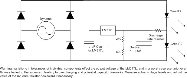
Here is my idea for a slightly better controlled standlight.

DynamoStandby.jpg

Thanks to znomit for putting this image up for me

The LM317L initially steals 100mA from the dynamo to charge the supercap, but once charged - to 5.3V (in 10s for a 1F 'Amp-type' super cap) - current consumption drops to 5mA (this is unavoidable as the 317 needs its voltage setting resistors to draw 5mA).
This reduction in current once charged is a distinct advantage over zener-based charging schemes which keep drawing current after charging.
There is also a simple one transistor circuit that can be used, except that it needs more supporting components.
Other 5V 100mA three terminal regulators could be user, but they have to tolerate big capacitors on thier output when the input is open circuit. not all can cape with this like the 317 can.

Charging the supercap to close to its maximum voltage means that it stores more energy than charging it to only 3.6V, so more standby time.

EDIT - Following Alex Wetmore's work (see further down), I should point out that tolerance build-up can cause this circuit to produce more than 5.5V.
So if you build it, check the output voltage and reduce the value of the 820 Ohm resistor if the output turns out to be too high.

The resistor sets the initial discharge current.
So for 20mA - which would last quite a while but not be very bright -
for 20mA chose V/I=R = (5.3-3.6)/0.02=85ohms.

If using a 'mA' type supercap, subtract its internal resistance (from its data sheet) from the resistance you get from the calculation. mA types will charge slower.

The asterisk indicates where a diode would be required to protect the 317 if either the top led, or the bridge rectifier, leaked more than a few mA.
But as they don't, no diode is needed.

The 0.1uF input capacitor is required for stability on the input of the 317.

This circuit is untesed, but the 317 is a pretty predictable beast.

Steve
 
Last edited:

StevelKnievel

Newly Enlightened
Joined
Oct 13, 2007
Messages
114
Re: Will this circuit work?

That's a nice idea! I toyed with the idea of IC regulated cap charging a few months ago but I kept coming up with overly complex ideas... This is as simple as it gets! I like the fact that you can control output current from the fully charged supercap, I bet this setup will yield some exceptional standlight runtimes! Also, it seems that the circuit can be scaled up for more LEDs. Check me if I'm wrong here, but with a few component swaps you could set it up to run 2LEDs from a 3LED array or 3LEDs from a 4 LED array. I like it!
 

Steve K

Flashlight Enthusiast
Joined
Jun 10, 2002
Messages
2,786
Location
Peoria, IL
Re: Will this circuit work?

hey Mr. Bandgap,

As a long-time user of the LM317, I can't help but notice that you haven't included a protection diode connected from the output to input of the regulator. The datasheet recommends one in the event of a shorted input, but the circuit should be protected from that.

The datasheet also has an "absolute max" rating for the input-output voltage of -0.3v, and it seems possible that this might be exceeded. Of course, this usually assumes that the current could be significant. In this circuit, the current would be limited to the leakage current of the diode bridge in addition to whatever the upper LED would conduct at a very low Vf.

Was the omission intentional, and if so, what was the justification?

Overall, I think this circuit strikes a nice balance between "ultra simple but short run time" and "very complex but long run time".
I'll still be using a nicad and the Zetex boost circuit, though. :)

good to hear from you again!

Steve in Illinois
 

FrontRanger

Newly Enlightened
Joined
Oct 22, 2007
Messages
166
Location
Colorado, USA
Re: Will this circuit work?

The 0.1uF input capacitor is required for stability on the input of the 317.

Many people use a "smoothing" cap that appears in parallel with the 0.1 uF input cap shown here, and it is typically 4 to 5 orders of magnitude larger than this input cap. I assume the 0.1 uF input cap forms the dominant pole of the loop? If so, retaining the "smoothing cap" should not be a stability problem. It will just take longer for the loop to settle.
 

syc

Newly Enlightened
Joined
Jun 10, 2008
Messages
155
Re: Will this circuit work?

Here is my idea for a slightly better controlled standlight.


Cool! I've tried to work your mods into the original drawing. Please tell me if this drawing is accurate:

2981390077_ea2e2208a1_o.jpg


I'm assuming that this standlight charging circuit could just be dropped in Martin's circuit 8 in between C1 and the LEDs in his design? If the goldcap were a pair of 1.5F supercaps in series instead of a single, how do the internal resistances of the caps in series fit into the calculation for the discharge rate resistor? Do you just subtract the sum of both internal resistances? I guess it might also be necessary to change the values of the control resistors for the LM317L so that it sets a different max voltage for the supercaps in series?

Thanks again!
 
Last edited:

Bandgap

Enlightened
Joined
Aug 14, 2002
Messages
284
Location
London
Re: Will this circuit work?

That's it.

Except the left hand capacitor is not a smoothing cap, but an 0.1uF stability cap for the regulator.
It has only a tiny smoothing effect on the main voltage waveform.
It should be near to the pins of the regulator chip.

As I said somewhere above, I am not a great fan of big smoothing capacitors on dynamos unless you have hub dynamo and you spend a lot of time cycling below 6mph (10km/h)
If you must have a big smoothing capacitor, you must put Steve K's diode in - see below in this post - or put a diode in the asterisk position and keep the smoothing capacitor up-stream of this.

FrontRanger
It is years since I understood poles and zeros!
I think it is the impedance of the capacitor at potential oscillation frequencies that is important.
Big electrolytic capacitors tend to have quite high impedance in the MHz range where I suspect the 317 would oscillate if it has the chance.
Mid-sized ceramic capacitors have low impedance at low-MHz frequencies.

Overall
A 0.1uF ceramic (I would use a modern multi-layer ceramic) right close to the pins of the LM317 will keep it happy. There things are only 5x5mm at the biggest.
It is the price you pay for bringing in an electronic regulator.

This is National Semiconductors take on that particular capacitor from the LM317L data sheet http://cache.national.com/ds/LM/LM317L.pdf :
"An input bypass capacitor is recommended in case the regulator is more than 6 inches away from the usual large filter capacitor. A 0.1μF disc or 1μF solid tantalum on the input is
suitable input bypassing for almost all applications. The device is more sensitive to the absence of input bypassing when adjustment or output capacitors are used, but the above values will eliminate the possibility of problems."

Syc
I am not sure having caps in series would gain you anything except the ability to have both leds on when stopped.
You will have a tough job charging two 5.5V caps in series using a similar arrangement because to get them full, you would need at least 11V from somewhere to charge them.
And the 317 needs a volt or two to work.
And unless they are hand-selected for balance, supercaps in series need some kind of balancing or limiting circuit (like an led directly across each one) if they are to be reliable - not difficult, but more hassle.
Aside from the cosmetic difference, if you need more light you might as well put twice the (small) current through the one led that is easy to drive.
If you have two caps, put them in parallel and get a longer or brighter standby.
For the record, the resistances of series capacitors add.
The resitances of parallel capacitors is a bit more complex, but for identical capacitors you divide the series resistance of one by the number of capacitors.
If integrating with Martin's circuit 8 http://www.candlepowerforums.com/vb/editpost.php?do=editpost&p=2679207, feed the 317 and its little capacitor from the top of LED5, and connect the discharge resistor to the centre point of LED5 and LED6.

Steve K
Most excellent to hear from you again.
My justification for missing out a diode from output to input is: AFAIK, the internal junction can take care of small leaks.
Providing you do not have an external low impedance conduction path from input to anywhere important, you don't need an external diode across the output-input, or in series with the input.
So long as there is no big smoothing capacitor, and you stick below the reverse breakdown voltage of the led, this design has no low-impedance paths from the input of the 317.
For reference: the data sheet says: "The discharge current depends on the value of the capacitor, the output voltage of the regulator, and the rate of decrease of VIN. In the LM317L, this discharge path is through a large junction that is able to sustain a 2A surge
with no problem. This is not true of other types of positive regulators."


Phew.

Steve
 
Last edited:
Top