Coming from a software engineer, I'm sure this is a dumb question! Is there a reason to still have a voltage doubling circuit when you have a supercap standlight? I'm trying to decide whether it's worth the extra complexity... I've been using a simple dynamo circuit on my my headlight as I usually have a battery powered helmet light too, but I'm looking to get rid of the batteries for multi-day trips.
You are using an out of date browser. It may not display this or other websites correctly.
You should upgrade or use an alternative browser.
You should upgrade or use an alternative browser.
Standlight vs Voltage Doubler
- Thread starter mbanzi
- Start date

Steve K
Flashlight Enthusiast
the voltage doubler option exists to provide more light at low speeds. This is more of an issue when running more than 3 LEDs in series. If you don't need it, then there's no point in having it.
Thanks Steve! The light will be used at low speeds & my plan is to use 3x XM-L2 or XP-G2 LEDs with my Shutter Precision dynamo, so I may take a look at your circuit again. I was actually considering using the supercap charging circuit out of your "TwoLED with standlight" (https://www.flickr.com/photos/kurtsj00/15674268650/in/album-72157649424813991/) and putting it into the "SonOneTwo with standlight" (https://www.flickr.com/photos/kurtsj00/7483782976/in/album-72157621965148305/) circuit in place of the battery. Do you think that'll work?
Being a software guy, I'm still trying to figure out a solution for all this using an Atmel MCU, possibly one of the ATtiny models. I've done a fair amount of open source software & hardware, so this could be a fun project for the winter. I remember you mentioned using a MCU in an old post too.
Being a software guy, I'm still trying to figure out a solution for all this using an Atmel MCU, possibly one of the ATtiny models. I've done a fair amount of open source software & hardware, so this could be a fun project for the winter. I remember you mentioned using a MCU in an old post too.
the voltage doubler option exists to provide more light at low speeds. This is more of an issue when running more than 3 LEDs in series. If you don't need it, then there's no point in having it.
Steve K
Flashlight Enthusiast
there shouldn't be any problem with using the supercap standlight circuit with the SON-one-two circuit. The two functions are pretty independent.
An Atmel should be a good replacement for the dual one-shot circuit for detecting when the dynamo is above or below the threshold speed. It might even let you do a little debouncing and control the hysteresis too. You'll need to add some sort of voltage regulator for the Atmel's supply, though. The 4000 series CMOS that I used is tolerant of a wide range of supply voltages.
When I get some spare time, I'm planning to play with the Atmel uC's myself. I used to do some RTOS stuff with 6811s some time ago. A micro gives you so much ability to monitor and control stuff that is difficult to do purely with hardware. Hardware does have the advantage that if it works once, it'll probably work forever. I couldn't say that about my software. :-/
znomit
Enlightened
If you're running a second light you probably don't need the doubler on a 3 LED circuit. You get an extra watt of light below 10kph. I guess if you're riding technical trails in the dark it would be useful.
http://www.pilom.com/BicycleElectronics/DynamoCircuits.htm#DualMode
http://www.pilom.com/BicycleElectronics/DynamoCircuits.htm#DualMode
Agree with Znomit - keep it simple. I've built the doubler circuit. It's good if you are on technical trails with very variable speeds and (as suggested) you are using 3 or more LEDs that need a bit of voltage to fire up. But you actually don't need more that 1 or 2 LEDs for most purposes! I'd focus on a 2 LED headlight with a decent stand light on one LED and then integrate it with a tail light, also with standlight. The recent Standlights for Dummies thread may be instructive...
Savvas (NOT a software engineer - unfortunately...)
Savvas (NOT a software engineer - unfortunately...)
Simple hah! Here's my objective: I do a lot of multi-day bikepacking, often we end up on technical trails at night. Typically I won't be using a second light. My plan is to build a system with the following features:
Here's my plagiarized & *******ized design so far, any advice/comments will be appreciated:

Briefly:
Questions:
As I mentioned before, I'm a software guy, I just fake my way around the hardware. Eventually I want to get rid of the doubler circuit & add a MCU controlled switching power supply with MPPT. Would be nice to handle the LED switching with the MCU too. Possibly counting the dynamo's AC cycles to figure out the bike's speed?
- Light head with 3x Cree XP-G2 LEDs & Carclo optics (triple LED star, light has to be SMALL)
- Shutter Precision PD-8X dynamo
- PCB with combined (switchable) doubler/standlight & USB device charger
- Mostly surface mount components (why make it easy)
- 1xLED on standlight
- 2xLEDs on doubler
- 3xLEDs at speed
Here's my plagiarized & *******ized design so far, any advice/comments will be appreciated:
Briefly:
- Dynamo is rectified with DMHC3025LSD mosfet H-bridge
- Rectified output always goes to 5V regulator
- Selector switches: rectified output to doubler & standlight, also 5V to USB charger
- 5V Regulator use an adjustable low dropout MIC29152WD reg
- USB charger uses a TPS2514 auto selector IC on the data lines & a AP2822KA USB switch for protection
- The doubler & standlight is a combination of Steve K's circuits
Questions:
- As the Cree XP-G2 have a lower Vf of 2.8V @ 350mA, do any values need to change?
- I need to turn off the dynamo input. Where in the circuit would the ideal location for a system switch be?
As I mentioned before, I'm a software guy, I just fake my way around the hardware. Eventually I want to get rid of the doubler circuit & add a MCU controlled switching power supply with MPPT. Would be nice to handle the LED switching with the MCU too. Possibly counting the dynamo's AC cycles to figure out the bike's speed?
Steve K
Flashlight Enthusiast
With a quick look at the circuit, a few issues/concerns come to mind....
1. the mosfet bridge rectifier is handy, but doesn't block reverse current. This will be a problem when using filter caps, such as the 10uF in front of the 5v regulator. You may want to add a schottky diode in front of the 10uF cap to keep it from discharging on every AC cycle of the dynamo.
2. On my circuit that shorts out two LEDs at low speeds, I can barely notice when all four LEDs turn on. The eye is just not very sensitive to changes in light levels. In this design, the change is from 2 LEDs to 4 LEDs, and my guess is that you'll never notice the change.
3. in my circuit, I've always got a load on the dynamo that draws 0.5A. The bidirectional TVS diode at the input is there to protect the rest of the circuitry if a wire opens up (probably due to a sloppy solder joint?). It's not a big diode, and won't handle the power for long. It'll eventually fail shorted, which is okay, because it'll still protect the rest of the circuit and I'll need to get into the light to fix the open wire anyway. In this circuit, when charging the battery, the draw from the dynamo may drop to zero, causing the TVS diode (or equivalent zener) to have to absorb the 0.5A from the dynamo. If it's a 7.5V diode, that means that it will dissipate roughly 4 watts of power. You'll want to use a 5 watt zener and heatsink it to the housing to get the heat out. and honestly,... I don't recall the power rating of the TVS diode that I used. I just recall it as being smaller than a 5W zener.
3. The "speed switch" circuit was set up for the SON 28 dynamo that I use. If the SP hub has a different number of poles, the speed at which it switches will be different. You'll probably want to adjust the timing circuit to get the switching to happen at the appropriate speed for your dynamo and # of LEDs regardless.
4. I didn't find any data on the AP2822KA... does it mind having the input power go away now and then?
5. for this circuit, the collector of Q1 could be connected to the anode of LED2 instead of the cathode, which would allow the elimination of the D5 schottky diode.
regarding your questions:
The different Vf values shouldn't make any significant differences.
To turn off the dynamo, I'd just add a switch in series with the dynamo.
Replacing the dual one-shot circuit with a little uC would be nice. The AC frequency is fairly low, so measuring the time from rising edge to falling edge is probably better and faster. ...or rising edge to rising edge, etc.
Thanks for the reply & comments Steve.
Hmm, I forgot you're not supposed to use a FET bridge in front of a capacitor input power supply, the schottky is a good idea.
Are you saying I should just drop the doubler circuit? I use 3 LEDs BTW.
Good point, 5 watts is a decent amount of heat to dissipate. I'll have to think about this.
I believe the Shutter Precision dynamo also has 26 poles like the SON 28.
Should be ok looking at the AP2822 Datasheet
Does that mean the standlight will be driving 2 LEDs?
1. the mosfet bridge rectifier is handy, but doesn't block reverse current. This will be a problem when using filter caps, such as the 10uF in front of the 5v regulator. You may want to add a schottky diode in front of the 10uF cap to keep it from discharging on every AC cycle of the dynamo.
Hmm, I forgot you're not supposed to use a FET bridge in front of a capacitor input power supply, the schottky is a good idea.
2. On my circuit that shorts out two LEDs at low speeds, I can barely notice when all four LEDs turn on. The eye is just not very sensitive to changes in light levels. In this design, the change is from 2 LEDs to 4 LEDs, and my guess is that you'll never notice the change.
Are you saying I should just drop the doubler circuit? I use 3 LEDs BTW.
3. in my circuit, I've always got a load on the dynamo that draws 0.5A. The bidirectional TVS diode at the input is there to protect the rest of the circuitry if a wire opens up (probably due to a sloppy solder joint?). It's not a big diode, and won't handle the power for long. It'll eventually fail shorted, which is okay, because it'll still protect the rest of the circuit and I'll need to get into the light to fix the open wire anyway. In this circuit, when charging the battery, the draw from the dynamo may drop to zero, causing the TVS diode (or equivalent zener) to have to absorb the 0.5A from the dynamo. If it's a 7.5V diode, that means that it will dissipate roughly 4 watts of power. You'll want to use a 5 watt zener and heatsink it to the housing to get the heat out. and honestly,... I don't recall the power rating of the TVS diode that I used. I just recall it as being smaller than a 5W zener.
Good point, 5 watts is a decent amount of heat to dissipate. I'll have to think about this.
3. The "speed switch" circuit was set up for the SON 28 dynamo that I use. If the SP hub has a different number of poles, the speed at which it switches will be different. You'll probably want to adjust the timing circuit to get the switching to happen at the appropriate speed for your dynamo and # of LEDs regardless.
I believe the Shutter Precision dynamo also has 26 poles like the SON 28.
4. I didn't find any data on the AP2822KA... does it mind having the input power go away now and then?
Should be ok looking at the AP2822 Datasheet
5. for this circuit, the collector of Q1 could be connected to the anode of LED2 instead of the cathode, which would allow the elimination of the D5 schottky diode.
Does that mean the standlight will be driving 2 LEDs?
Steve K
Flashlight Enthusiast
Are you saying I should just drop the doubler circuit? I use 3 LEDs BTW.
mostly I'm saying that you should either just use 2 LEDs, or use 4 LEDS and short out 2 at high speeds.
or use Martin's doubler circuit with the 3 LEDs?? I haven't used it, so I can't comment on its effectiveness. He seems to have plenty of documentation, though.
Should be ok looking at the AP2822 Datasheet
neat part! I didn't realize it was "just" a switch.. for some reason I was thinking that it might control the charging of the battery that was plugged in, but now I assume that you let the device that is plugged into the USB port control its own charging.
Does that mean the standlight will be driving 2 LEDs?
whoops.. never mind... I had forgotten how I had things set up on my 4 LED light. The purpose of the schottky diode is to keep current from flowing back through the boost circuit's inductor and charging the supercap (and over charging the supercap).
piesoup
Newly Enlightened
Hi mbanzi, your ideas are very close to mine. You've managed to explain it better though! Steve helped me a lot in my previous posts. Cheers Steve!
I would want to include a cache battery in mine too.
Could the cache battery power the stand light and additional lighting if needed? I know that to recharge the cache battery you'd need extra power from the Dynamo. And it could run out if used for too long!
My diagrams aren't showing in my original thread, I will start a new one when I'm back at work and get them up. I plan to use an Arduino to control the switching of extra LEDS, charging of GPS or cache battery.
The generator I hope to use is a stepper motor. It puts out 7w at 1200rpm. Not sure how it'll survive at higher speeds though.
Andrew
Steve K
Flashlight Enthusiast
you could certainly include a cache battery. The bigger question is figuring out how you will control the charging and discharging of the battery, as well as determining how much power or energy the battery will need to supply to the loads, and how fast you need to charge it (and how much power will be required from the dynamo, and how much will be left for the headlight).
These issues do require some sort of controller, I think. Managing the standlight, controlling the battery charge & discharge, monitoring the dynamo status (is it stopped? Is it going slow? How much power can be extracted from it, and how?)... these things need to be taken care of.
Many years ago, I worked with a satellite power system. It took power from the solar panels, charged the batteries, and then provided power to the satellite. To some degree, I see the bike light as being similar, especially once you add a battery and extra loads. I did try something similar to this, over 10 years ago, and my control circuitry wasn't good enough (and power LEDs weren't available yet). As a result, I've reduced my power storage requirements quite a bit and made the battery charging and discharge circuits as minimal as possible.
I do have plans to play with microcontrollers and try something more sophisticated, but that is still a little ways away.
I've actually made some progress since I last posted here. As I need this light to be working by the end of January, I decided to use Steve's supercap standlight circuit combined with his voltage doubler. The USB charging side I used mostly my own circuit that I've used before successfully. What I like to do when prototyping projects like this is to break it up into small modules that I can test individually. So far I've tested the MOSFET rectifier & USB charging modules:


I hooked up a star with 3x Cree XP-G2 LEDs in serial directly to the rectifier & was very impressed!
Next up will be the 5V supply circuit. I typically will keep this simple and just use a LDO regulator, but I had a Linear LTC3114-1 lying around, so I decided to make a buck-boost supply. I'm not really impressed with the boost performance while simulating in LTSpice, so I may switch it out for the LTC3112 which looks a lot better in simulation but will need to be clamped at 15V. Still not convinced that I really need the boost circuitry...
Version 2 of this design will use a microcontroller to drive a switching supply, continuing minisystem's work somewhat. I plan to use a Incremental Conductance MPPT algorithm to maximize power output to the light. I had also thought of using N-channel MOSFETs to switch LEDs out of the serial configuration in place of the voltage doubler. Initially I considered using an opto isolator & a zero cross detector algorithm on the microcontroller to detect the AC frequency & calculate the bicycle's speed, but seeing as how we're already measuring voltage for MPPT, the LEDs can be switched based on output voltage. I'll post the schematics at some point which explains this better.
I like the idea of charging a battery too with the USB charging circuit, may incorporate that in V2. I was looking at the Adafruit PowerBoost 1000 for ideas which can charge a battery & USB device at the same time. I'm sure you would be able to drive the standlight from the battery, but I seem to recall that a LiPo battery doesn't like the constant small discharge/charge cycles. Anyone know this for sure?
I'll keep updating this thread with my progress - not much of a blogger!
Hi mbanzi, your ideas are very close to mine. You've managed to explain it better though! Steve helped me a lot in my previous posts. Cheers Steve!
I would want to include a cache battery in mine too.
Could the cache battery power the stand light and additional lighting if needed? I know that to recharge the cache battery you'd need extra power from the Dynamo. And it could run out if used for too long!
My diagrams aren't showing in my original thread, I will start a new one when I'm back at work and get them up. I plan to use an Arduino to control the switching of extra LEDS, charging of GPS or cache battery.
The generator I hope to use is a stepper motor. It puts out 7w at 1200rpm. Not sure how it'll survive at higher speeds though.
Andrew
Steve K
Flashlight Enthusiast
sounds very interesting! Do you have schematics?
I'm interested in hearing about the plans for version 2 too. You mention using a micro to control a switching power supply, but also mention switching out LEDs. It doesn't seem like both of those should be needed.
I'm interested in hearing about the plans for version 2 too. You mention using a micro to control a switching power supply, but also mention switching out LEDs. It doesn't seem like both of those should be needed.
Thanks Steve, your input is always appreciated. This where my lack of understanding of the hardware basics kick in! Wouldn't there be a point (at lower speeds) that the LED Vf would get too high to produce any light output (especially with 3xLEDs in series)? How would the switching supply overcome this? I was thinking I would switch out on LED to overcome this.
sounds very interesting! Do you have schematics?
I'm interested in hearing about the plans for version 2 too. You mention using a micro to control a switching power supply, but also mention switching out LEDs. It doesn't seem like both of those should be needed.
Steve K
Flashlight Enthusiast
Thanks Steve, your input is always appreciated. This where my lack of understanding of the hardware basics kick in! Wouldn't there be a point (at lower speeds) that the LED Vf would get too high to produce any light output (especially with 3xLEDs in series)? How would the switching supply overcome this? I was thinking I would switch out on LED to overcome this.
well, if you are trying to match the output capabilities of the dynamo to one or two different loads (LEDs and battery), then it is important to understand the details of the dynamo and the loads. When I designed a peak power tracker for solar panels, I had to know how the panel's voltage-current characteristics changed over temperature and illumination. With the dynamo, it's important to have similar knowledge. Back in the days of the Bikecurrent mail list, a fellow named Nick Ray gathered data on the SON28 dynamo. He spun the dynamo at different speeds and loaded it with a range of resistances. With this data, you can know what the optimal resistance for the load will need to be in order to get the most power from the dynamo. You'll need to know this if you are going to be able to judge whether your MPPT is working correctly.
Here's a table of data that Nick produced....
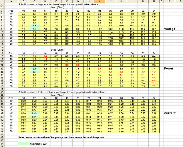
As you can see, the dynamo voltage is proportional to the speed, so there are speeds where it can't forward bias three LEDs in series. I've seen this in my daily commute, where I have to climb a hill that limits my speed to 4 mph or so. This will barely forward bias two LEDs.
Switching power supplies are useful because their input resistance varies with the duty cycle. Also, a buck converter effectively has a negative input resistance. For instance, if you use a buck converter to provide a fixed amount of power to a load, the input current decreases as the input voltage increases.
A MPPT could use a buck converter as the load for the dynamo, and adjust the duty cycle in order to change the resistance that loads the dynamo. This would allow the controller to get the maximum amount of power from the dynamo.
This part is possibly the easy part. The harder part, IMHO, is the control loop algorithm. The algorithm will have to deal with the AC power from the dynamo, which makes it harder to make a reading of the voltage, current, or power at a given time. The algorithm has to somehow measure the output power, or at least measure whether the output power goes up or down when changing the load. This might be difficult... depending on how it is done. There is also the issue of battery charging... will you provide power to a separate battery charge controller chip, or will the microcontroller do it? Do you want to charge the battery in parallel with the LED load, or will you charge the battery and have the LEDs powered from the battery?
Lot of things to think about.
")
When I designed a peak power tracker many years ago, simulations make it easier to figure out whether a circuit would work or not, and to develop a control algorithm. There are problems with simulations too.. such as trying to simulate a switching power supply at the same time as simulating a low frequency device like a dynamo. Stuff happens very fast in the switching power supply, while things happen very slow in the dynamo. Sometimes you have to develop a very simple model of a device in order to make a complex simulation work. A simplified model of a switcher may be needed. Fortunately, Spice offers a variety of building blocks that can be helpful for developing models.
Or... just jump into things and see how far you get??
One thing that I've learned is that basic problems of physics and electronics don't go away just because I don't feel like dealing with them. On my headlight that switches from 2 to 4 LEDs in series, there was a weird tendency to switch back and forth between 2 and 4 LEDs at speeds around 14mph. It turned out that there was a weird oscillation in the dynamo voltage due to the way that the mosfets and LEDs would turn off. Careful observations with an oscilloscope helped define the problem. I was able to build a spice simulation of the circuit, using a suitable model for the dynamo, and was able to duplicate the problem in the simulation. This let me look at the various voltages and currents, which would be essentially impossible in the actual circuit. I found a fix, due to my knowledge of semiconductor behavior and theory. When the fix was implemented in the actual circuit, it worked!
details are in this Flickr album...
https://www.flickr.com/photos/kurtsj00/albums/72157621965148305
Wow thanks for the very comprehensive answer Steve!
Looking at the table, calculating speed to frequency & making a few assumptions, it looks like with my setup I will need around 4mph to drive 1 XP-G2, 11mph to drive all 3. Likely some kind of LED switching will be necessary? According to the Cree XP-G2 datasheet lowest Vf will be around 2.65V @ 95mA. I'll get a better idea once I have a test setup in place to spin the hub.
I'm not too concerned about the MPPT software. Generating PWM is trivial on the Atmel MCUs & using the ADCs to measure voltage & current is pretty simple too. Hopefully I can keep the hardware simple enough so my brain can deal with it!
As far as the battery is concerned, I haven't made up my mind whether to use one. I still like the supercap solution for the standlight, but a charged LiPo could be useful for charging devices at the end of a day. I like the Adafruit Powerboost's solution to use a MCP73871 System Load Sharing and Battery Charge Management Controller.
I'll post the schematics for V2 soon for your input.
As you can see, the dynamo voltage is proportional to the speed, so there are speeds where it can't forward bias three LEDs in series. I've seen this in my daily commute, where I have to climb a hill that limits my speed to 4 mph or so. This will barely forward bias two LEDs.
Looking at the table, calculating speed to frequency & making a few assumptions, it looks like with my setup I will need around 4mph to drive 1 XP-G2, 11mph to drive all 3. Likely some kind of LED switching will be necessary? According to the Cree XP-G2 datasheet lowest Vf will be around 2.65V @ 95mA. I'll get a better idea once I have a test setup in place to spin the hub.
I'm not too concerned about the MPPT software. Generating PWM is trivial on the Atmel MCUs & using the ADCs to measure voltage & current is pretty simple too. Hopefully I can keep the hardware simple enough so my brain can deal with it!
As far as the battery is concerned, I haven't made up my mind whether to use one. I still like the supercap solution for the standlight, but a charged LiPo could be useful for charging devices at the end of a day. I like the Adafruit Powerboost's solution to use a MCP73871 System Load Sharing and Battery Charge Management Controller.
I'll post the schematics for V2 soon for your input.
Steve K
Flashlight Enthusiast
Wow thanks for the very comprehensive answer Steve!
to some degree, this was just an exercise in reviewing my own dusty thoughts on this sort of project
It's definitely an interesting subject that no one has ever commercialized.
Looking at the table, calculating speed to frequency & making a few assumptions, it looks like with my setup I will need around 4mph to drive 1 XP-G2, 11mph to drive all 3. Likely some kind of LED switching will be necessary? According to the Cree XP-G2 datasheet lowest Vf will be around 2.65V @ 95mA. I'll get a better idea once I have a test setup in place to spin the hub.
In my 4 LED design that shorts out two LEDs at low speed, I used it for a while without circuitry, and with just a switch to short out the two LEDs. This let me evaluate what speed was appropriate for the change from 2 to 4 LEDs, and gave me an appreciation for how small the change from 2 to 4 LEDs is.... it really doesn't make a large difference in how well illuminated the road is. I had originally considered having circuitry to turn each LED on incrementally as speed increased, but it wouldn't have been worth the trouble.
I'm not too concerned about the MPPT software. Generating PWM is trivial on the Atmel MCUs & using the ADCs to measure voltage & current is pretty simple too. Hopefully I can keep the hardware simple enough so my brain can deal with it!
well... I do encourage people to develop an algorithm on paper before beginning a project. There will be enough problems just with the basics of hardware and software without having to figure out if your basic algorithm is flawed.
My main concern for a dynamo MPPT algorithm is handling the low frequency AC of the dynamo while trying to make small changes to the load and looking for whether the power increased or decreased. My history is with solar panels, which were nice enough to provide DC power. I was able to "dither" the load at a reasonably high frequency to make the control loop move along the voltage-current curve quickly. I suspect that this won't be able to be done with the dynamo. Perhaps the answer is to slow the control loop to average readings over a half second or so? Or synchronize measurements with the AC waveform so as to try to compensate for the sinusoidal changes? You could spend a fair bit of time just working out this detail!
There is also the issue of handling sudden dynamo speed changes. Not a big deal when speed is increasing, but when the speed decreases, you can quickly end up with very little output power. When working with a solar power tracker, there was a "collapse" detector circuit that would sense a quick decrease in the panel's output voltage and quickly change the setting for the buck converter so as to draw less power.
As far as the battery is concerned, I haven't made up my mind whether to use one. I still like the supercap solution for the standlight, but a charged LiPo could be useful for charging devices at the end of a day. I like the Adafruit Powerboost's solution to use a MCP73871 System Load Sharing and Battery Charge Management Controller.
I'll post the schematics for V2 soon for your input.
great!
You bring up points I hadn't even thought of. I could probably use hysteresis comparison to prevent the voltage collapse. The Incremental Conductance MPPT algorithm eliminates the oscillation at the maximum power point, but doesn't overcome voltage collapse. I think this will be a fun project with a lot of challenges!
My main concern for a dynamo MPPT algorithm is handling the low frequency AC of the dynamo while trying to make small changes to the load and looking for whether the power increased or decreased. My history is with solar panels, which were nice enough to provide DC power. I was able to "dither" the load at a reasonably high frequency to make the control loop move along the voltage-current curve quickly. I suspect that this won't be able to be done with the dynamo. Perhaps the answer is to slow the control loop to average readings over a half second or so? Or synchronize measurements with the AC waveform so as to try to compensate for the sinusoidal changes? You could spend a fair bit of time just working out this detail!
There is also the issue of handling sudden dynamo speed changes. Not a big deal when speed is increasing, but when the speed decreases, you can quickly end up with very little output power. When working with a solar power tracker, there was a "collapse" detector circuit that would sense a quick decrease in the panel's output voltage and quickly change the setting for the buck converter so as to draw less power.