Pastor of Muppets
Newly Enlightened
I really wanted to post this on LPF because the people there are the ones who sell the driver and diode I'm using. Unfortunately, the administrators won't approve me.
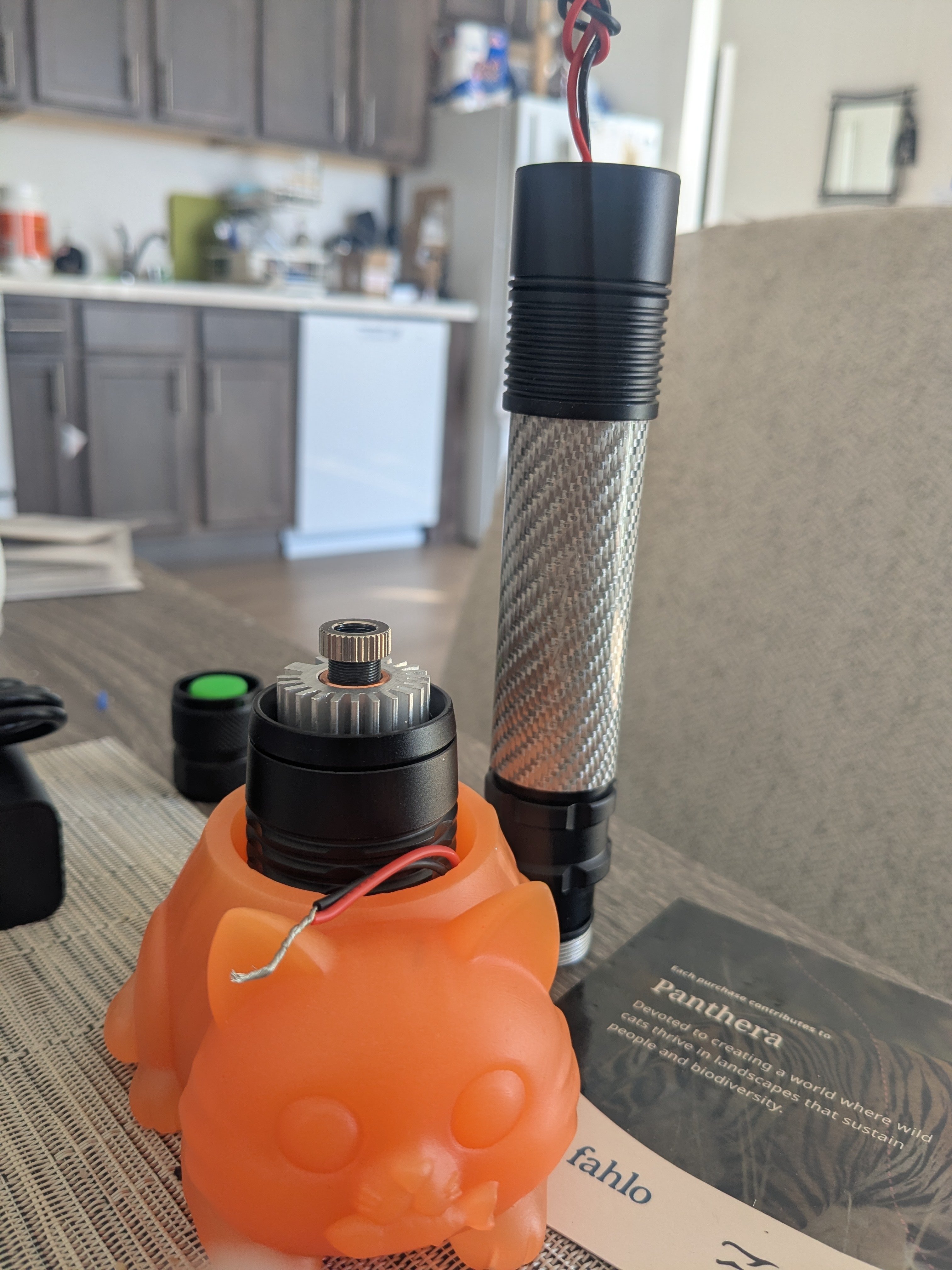
I have a micro flexdrive v5 that I purchased with the BDR-209 sold as a unit in aixiz housing from DTR's shop and a host from Z80 (Barnett Unlimited). The host came with battery board. I soldered the battery board to the driver leads. Worked fine (outside of the host, for obvious reasons). Then I installed in the host. Nothing. I took the unit out of the host, unsoldered from the driver board (to eliminate host \ board variables) and hooked the driver leads to an 18650: nothing.
I understand that the bare diodes are very susceptible to ESD shock. I understand that the diode being unsoldered to and from the driver board leaves the diode susceptible to ESD as well as damage from a charged capacitor upon hooking back up to driver board. I haven't had the bare diode out and I haven't disconnected from the driver board.
I've only hooked the driver up to a battery and to the battery board. Can a static shock damage the diode THROUGH the driver board ? Or could the driver board have been damaged by static shock ? The only thing I can think of is static shock, as I have purchased the module connected to the driver and didn't mess with anything except the + and - from the driver to the battery board. When the module (connected to the driver, since that's the way I bought it) was briefly tested, it was in the heatsink and was for 1 second, to make sure it worked before putting in the host.
I'm asking for any help in this matter. I don't know how to find what is damaged or understand why it got damaged.
Thank you in advance.
-Philippe
I have a micro flexdrive v5 that I purchased with the BDR-209 sold as a unit in aixiz housing from DTR's shop and a host from Z80 (Barnett Unlimited). The host came with battery board. I soldered the battery board to the driver leads. Worked fine (outside of the host, for obvious reasons). Then I installed in the host. Nothing. I took the unit out of the host, unsoldered from the driver board (to eliminate host \ board variables) and hooked the driver leads to an 18650: nothing.
I understand that the bare diodes are very susceptible to ESD shock. I understand that the diode being unsoldered to and from the driver board leaves the diode susceptible to ESD as well as damage from a charged capacitor upon hooking back up to driver board. I haven't had the bare diode out and I haven't disconnected from the driver board.
I've only hooked the driver up to a battery and to the battery board. Can a static shock damage the diode THROUGH the driver board ? Or could the driver board have been damaged by static shock ? The only thing I can think of is static shock, as I have purchased the module connected to the driver and didn't mess with anything except the + and - from the driver to the battery board. When the module (connected to the driver, since that's the way I bought it) was briefly tested, it was in the heatsink and was for 1 second, to make sure it worked before putting in the host.
I'm asking for any help in this matter. I don't know how to find what is damaged or understand why it got damaged.
Thank you in advance.
-Philippe
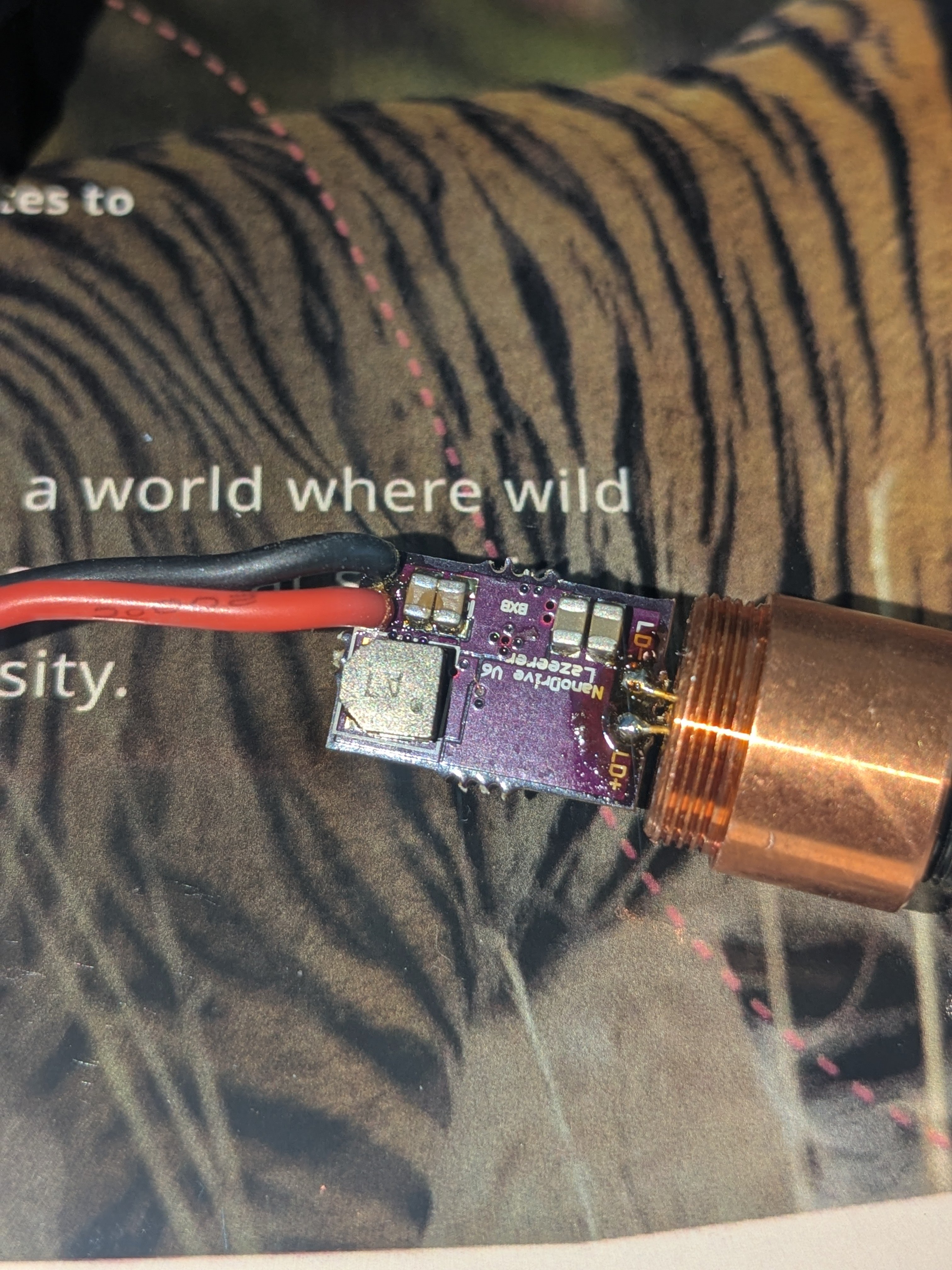
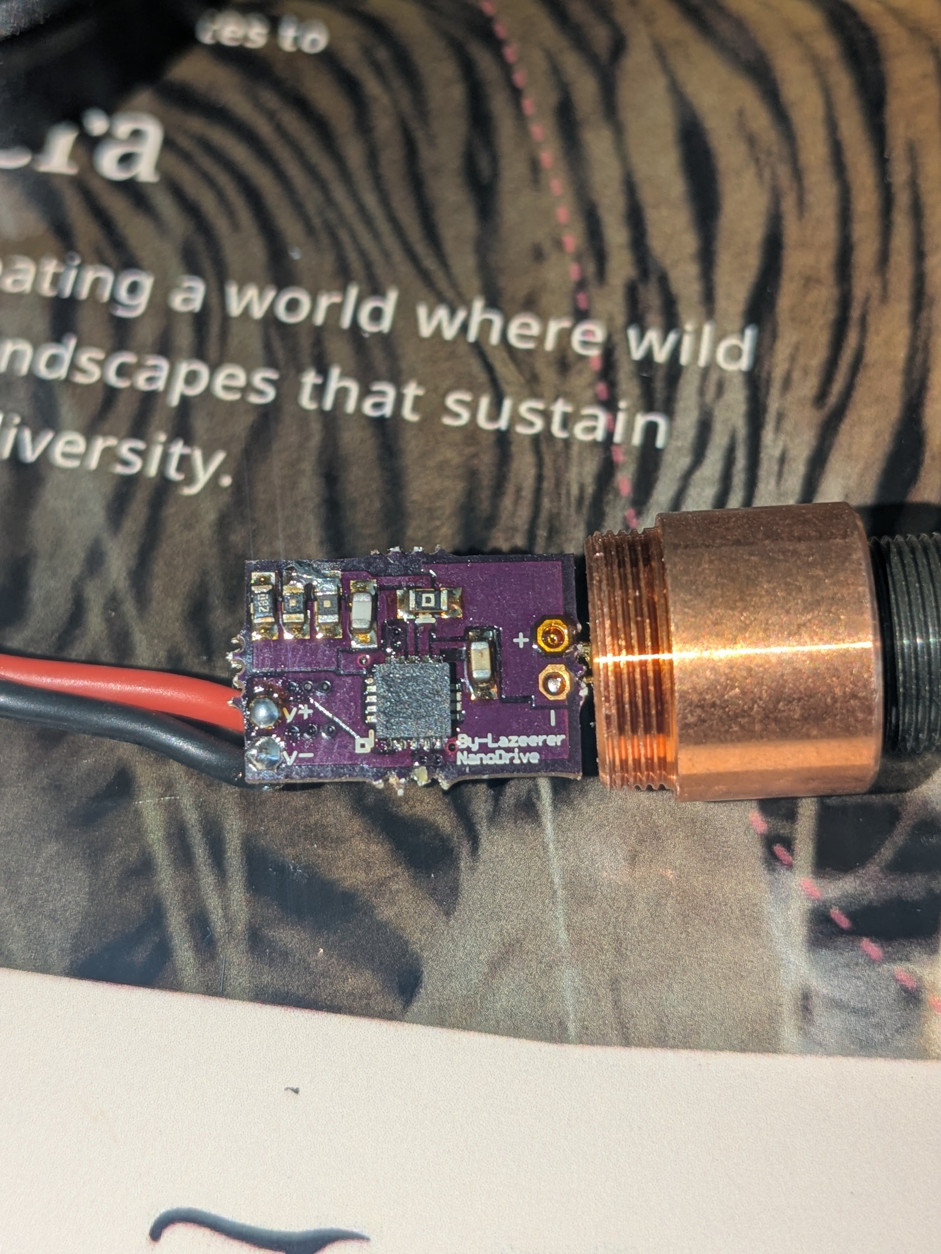
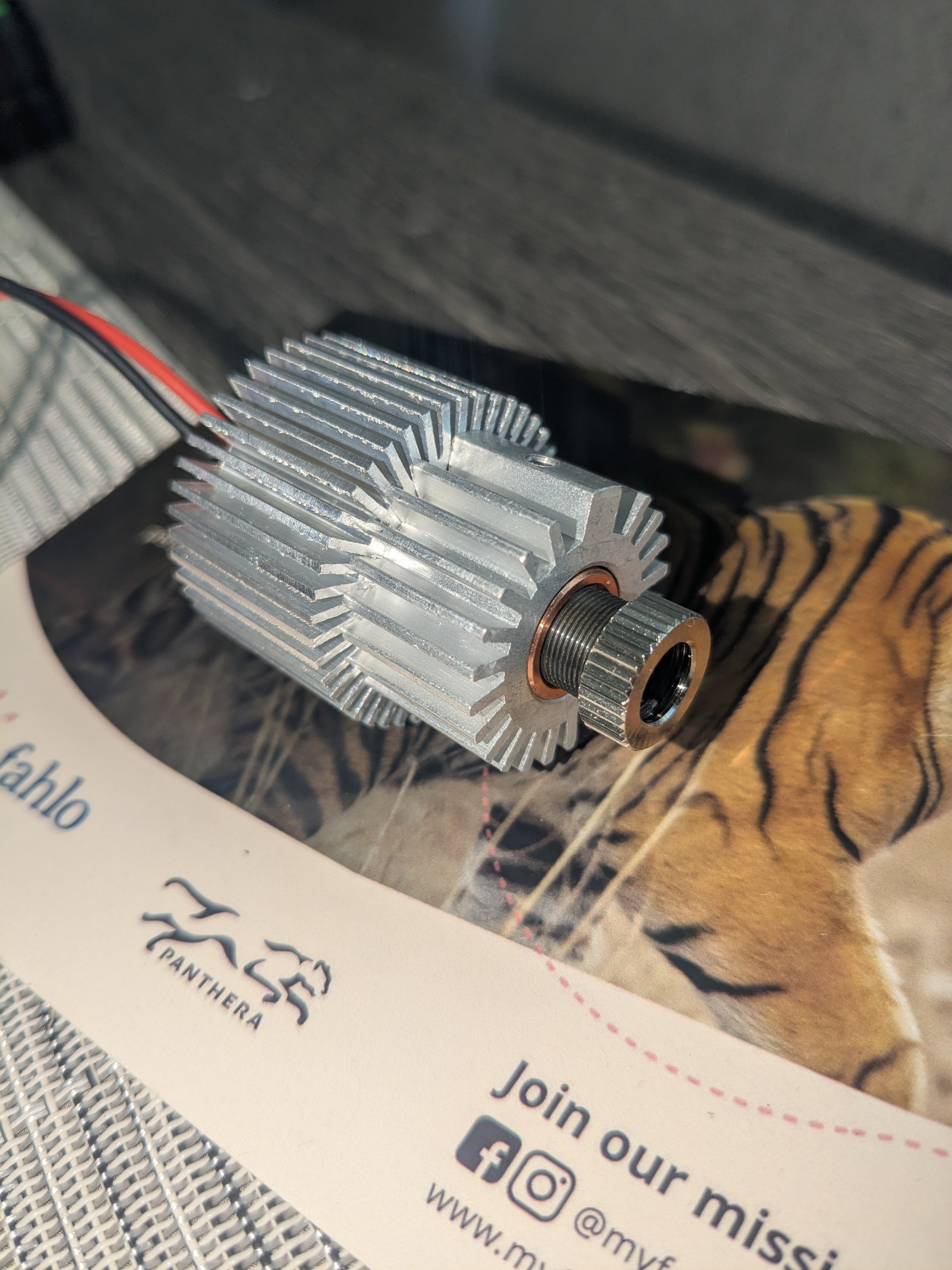

 ) and it was a 2 legged diode with a cold solder joint on the negative diode leg. Which was the leg I moved away from the PCB, assuming that it was the photodiode leg, because it was unsoldered. So I heated up my soldering iron, unplugged it, resoldered the negative diode leg and connected it to the driver. It worked. Now I probably semi-fried the driver by powering it with no load connected, but I was able to solder up the battery board and have a functional laser. It seems to have been a cold solder joint from the reseller (DTR Lasers). So, for a note to any other n00bs, check all your solder joints.