


HID mania
Newly Enlightened
"I am a very greedy person. I try to fit everything to myself like a perfactision."
The Maxa beam is excellent in every way and will be used alongside (or as a replacement for) the polarion I currently own in the future.
However, it is certain that there are a few points of dissatisfaction.
I have discovered numerous non-performance issues, such as the cooling design, room for weight reduction, low lumen values (in fact, the lumen figures are terrible... but the candela values are very good! - this is surmountable; I will elaborate on this in the main text below), reduced efficiency due to the use of older semiconductor components, and the thickness of the main power pattern on the PCB. I intend to modify these to suit my needs.
Caution: Maintenance by the headquarters (peakbeam systems) for this modified Maxa beam will likely be very limited.
Therefore, please "before the try this, and exercise caution and proceed with utmost care."
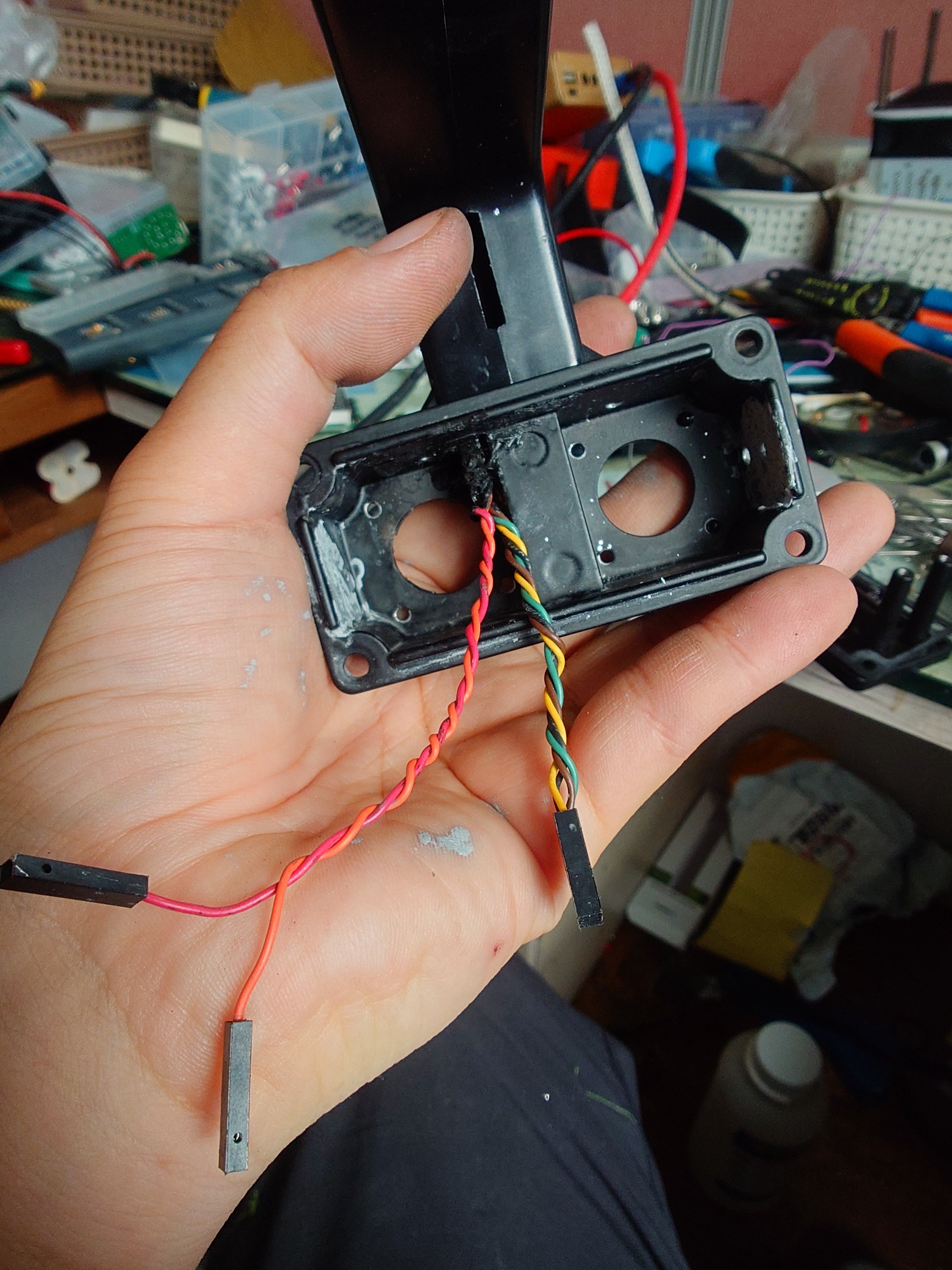
1. Back cap and control cables
->
The MBS 450 model has a total of two components blocking the rear: the "connector component for external control" and the "main power connector component."
However, to me, these components were completely useless.
First, the component for connecting the external control cable.
"Why is this necessary? I don't want to control this externally... :( Since it's not needed, I'll remove it without hesitation."
Twist the handle internal control cables neatly to organize them.
Second, the main power cable. In fact, the current capacity of the Maxa Beam's main power cable is likely significantly lower than that of the current 21century XT60. "I am removing the main power connector to install the XT60."
A word of caution: "You must keep the main power connector safe to have the flashlight serviced!!"
- According to the emails exchanged, they stated, "Modifying the main power connector is absolutely not recommended; without that connector, we cannot perform flashlight maintenance."
##### 1
We have secured two holes. Now, if we machine the circular center hole larger and slightly modify the square hole as well, we should be able to mount a 30x30mm cooling fan.
We anticipate that this will effectively resolve the heat generated by controlling the large current, given the characteristics of short-arc lamps where "low voltage and large current flow."
Furthermore, we expect this will help reduce power degradation caused by heat.
##### 2
I confirmed that supplying overvoltage (around 15V?) to the Maxa beam Gen.2 motherboard causes it to operate in "Lamp Overclock Mode."
Since this has been proven not only by me but also by a Maxa beam owner in Germany
(To summarize the story: "(He, like me, owns a 2nd generation model) One day, he accidentally input 30V into the Maxa Beam. It felt brighter than usual for some reason, but until then, he didn't realize that a whopping 30V was being supplied! Later, after replacing the lamp (which had exploded due to excessive overclocking), it surprisingly worked normally!")
and I have boldly decided to use the Maxa beam in an overclocked state at around 120W.
As this can also cause increased heat, it is expected that the additional forced air cooling system mentioned in ##### 1 will be necessary.
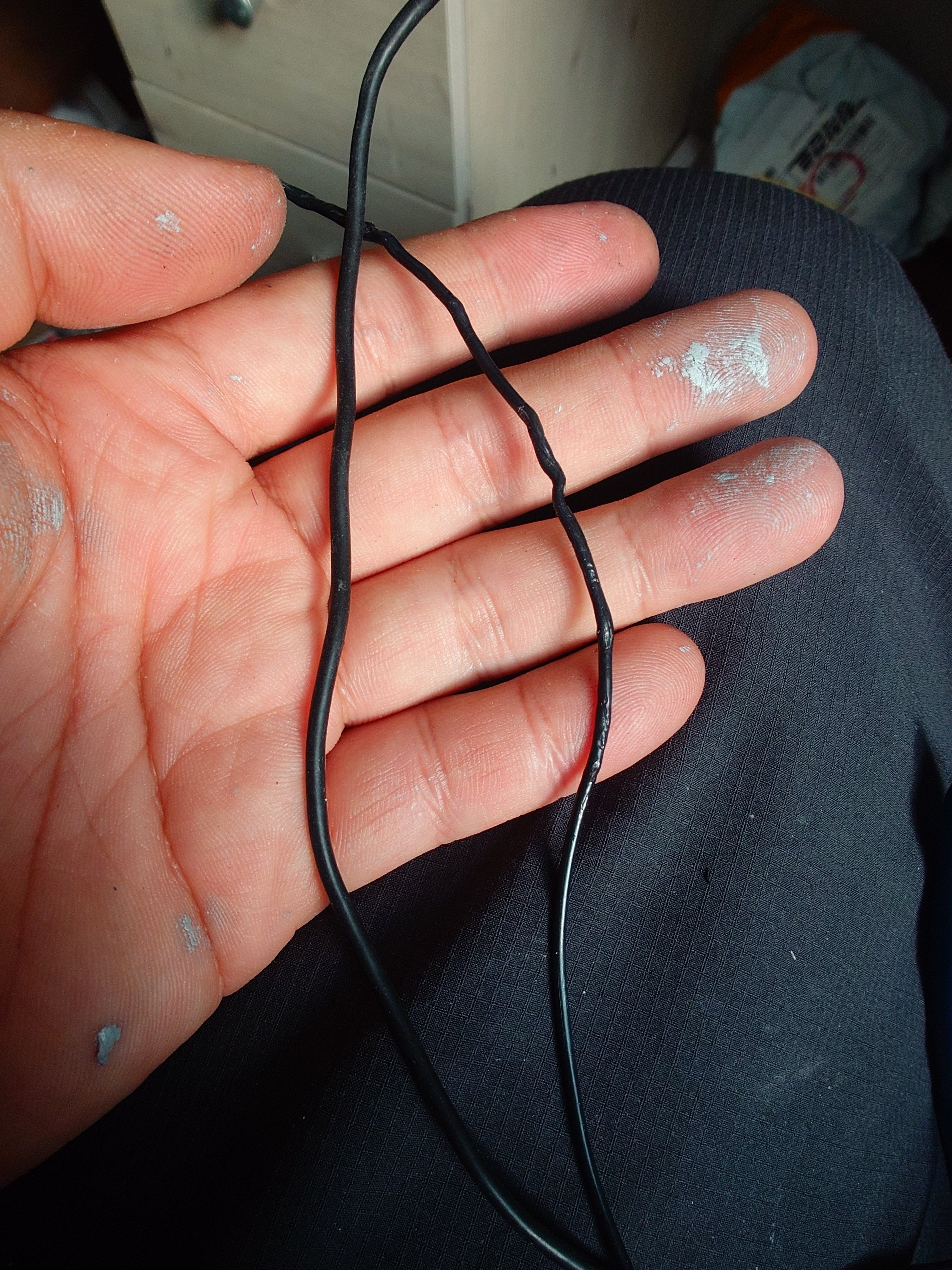
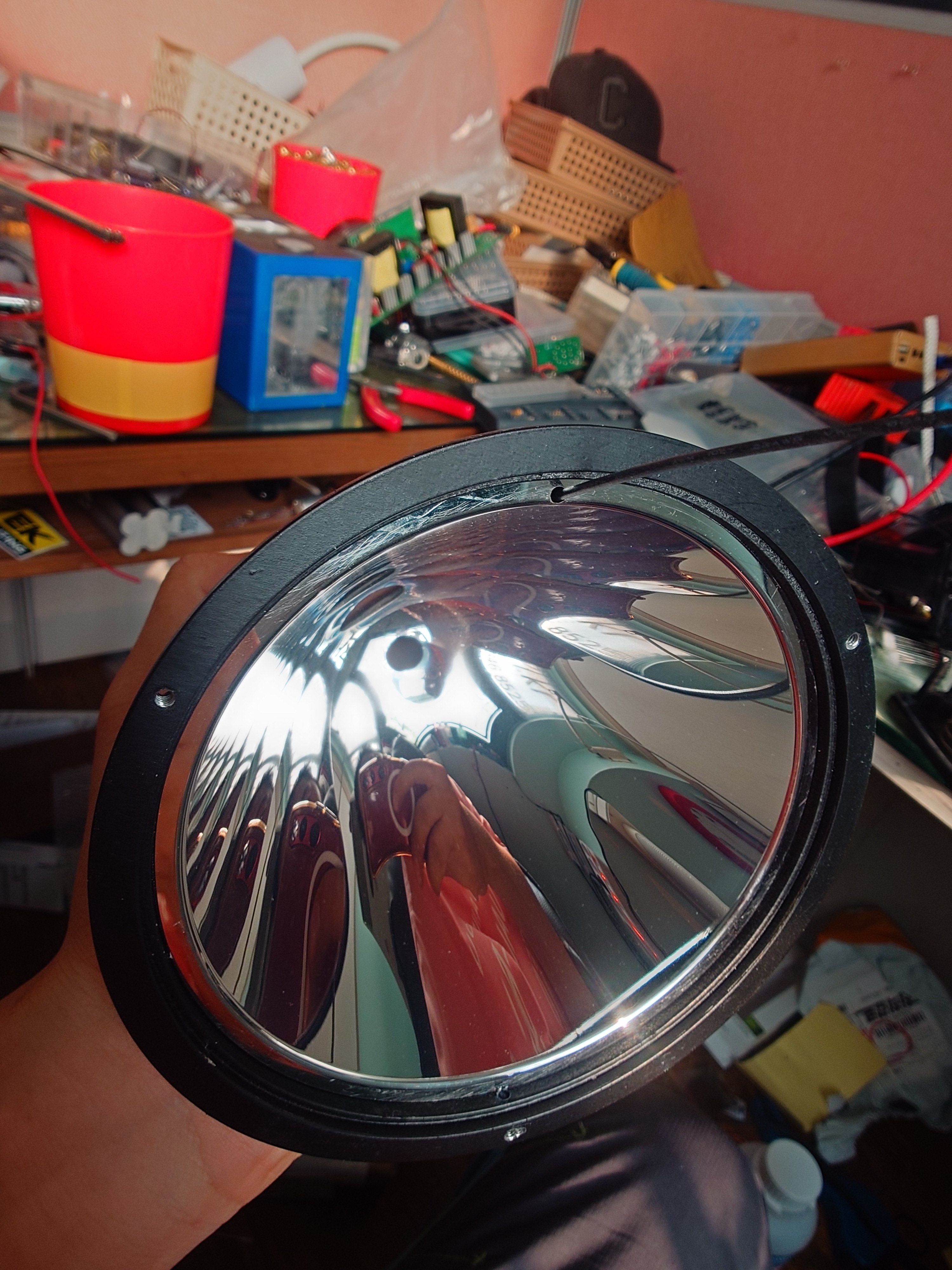
Change the "lamp power cable"
I determined that the standard lamp cable on the maxa beam is very rigid and inflexible, which could place excessive stress on the heated lamp. Additionally, the black color absorbs all light, potentially further reducing the maxa's already low lumen rating.
Consequently, I purchased "white silicone wire" and decided to solder it to the lamp connector. (I refer to the high-heat-resistant silicone wire commonly used in RC cars and drones.)
For soldering, regular solder must not be used. The heat generated by HID discharge lamps is beyond imagination.
I plan to use Mundorf's Silver-Gold Supreme solder. This solder contains nearly 10% pure silver, copper, and pure gold; it has excellent electrical conductivity but also a very high melting point (around 300 degrees Celsius? or higher?).
(Since both the solder and the wire are colors that reflect light well, I suspect that the temperature rise will not be high enough to cause the solder to melt and damage the connector.)
It is a really expensive and high-quality solder. In South Korea, standard solder costs about 4.5 USD, but the Mundorf Silver Gold Supreme solder being used in this project costs a whopping "500 USD (!!!!)" when calculated by weight—a completely insane price! Haha lol
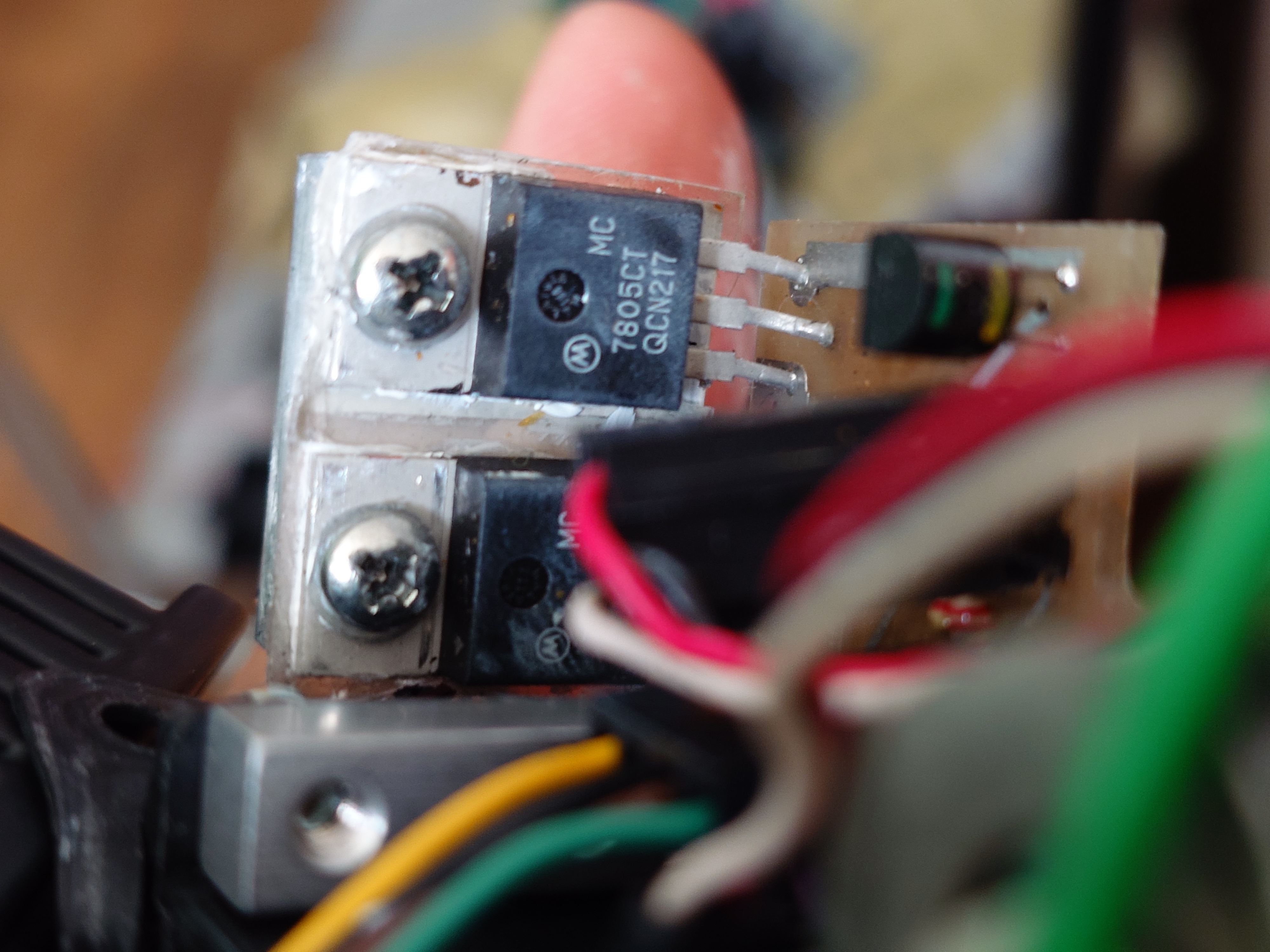
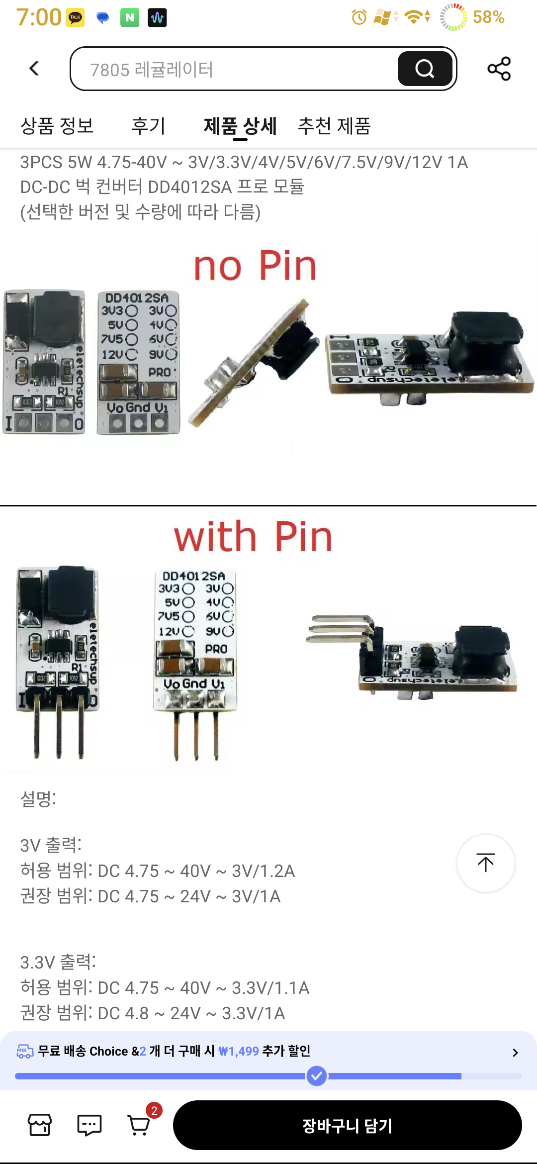
Nowadays, high-efficiency, ultra-lightweight, compact regulators are being released that can directly replace the 7805 with a 1:1 standard.
##### 3
If you replace it with such a regulator, you can remove the heat sink mounted on the 7805 and significantly reduce weight and heat generation.
On the opposite side of the 7805, an IRF 640 FET and a Schottky diode are installed.
I am still looking for a replacement diode (original maxa beam diode is a 0.7V Vf one).
The IRF 640 is also a relic of the past. Its Rds-on reaches a whopping 0.1 ohms.
FETs released nowadays with the same voltage rating are being manufactured with Rds-on ratings in the 0.0x ohm range.
I purchased the IPP069N20NM6AKSA1 to replace the IRF 640.
Although the gate charge is higher, I believe it will not be a significant issue, contrary to expectations. (The details will be fully verified during the interim project review later on...)
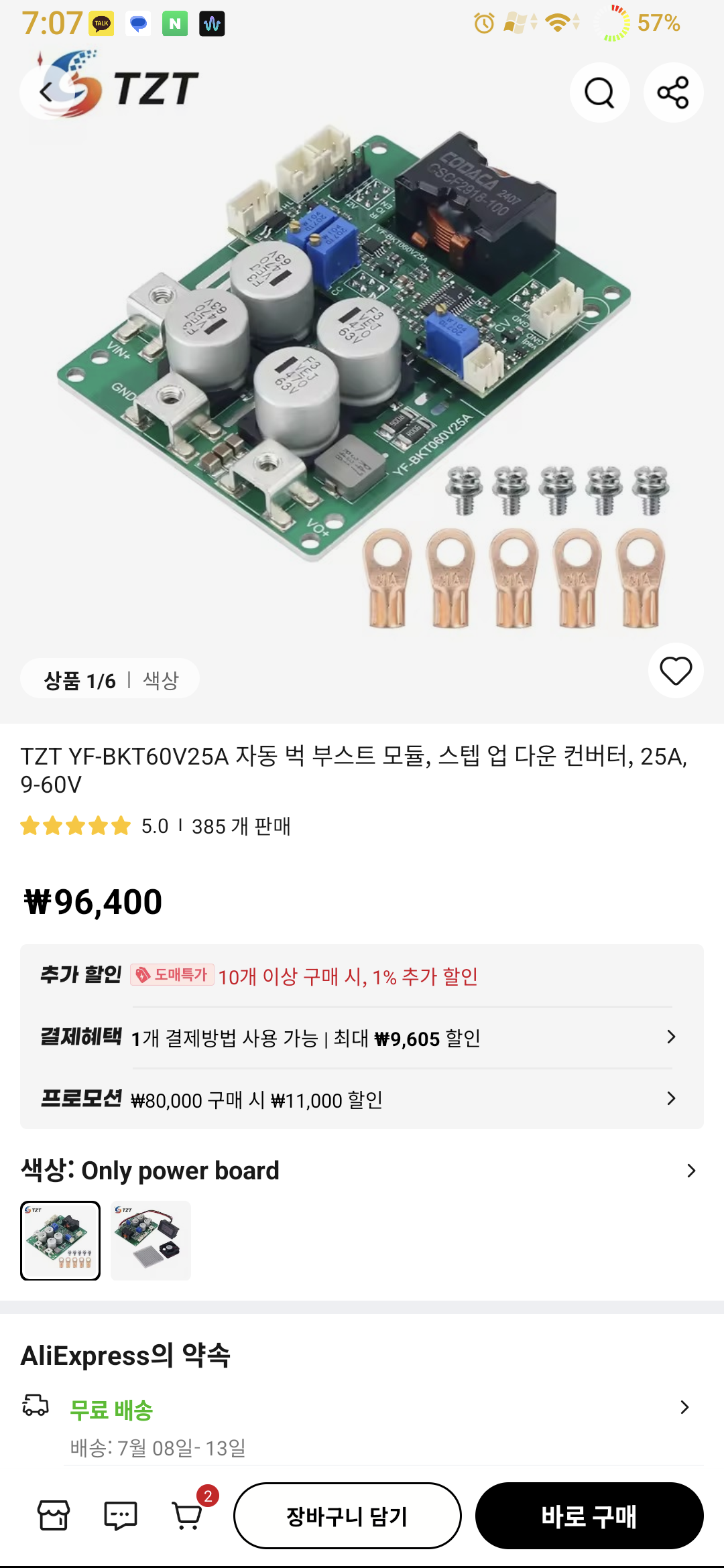
Plan of battery.
As previously mentioned, Gen.2 motherboards can overclock the lamps by supplying an overvoltage of approximately 15V.
To overclock the lamps, a transformer circuit will be used to supply a constant voltage. Additionally, since this circuit features a constant current function, it is expected to prevent accidents such as the lamp power running wild.
Furthermore, this circuit is designed to accommodate a separate on/off switch, which prevents the worst-case scenario of the battery draining incessantly when the device is left idle.(generally, converter circuit is 15~30mA consumption during ready time.)
The circuit board is constructed using a Metal PCB, which offers a structure more advantageous for heat dissipation. Consequently, this means that changes in settings caused by heat can be prevented more effectively.
##### 4
To speak about the overclocking the maxa beam test results...
Some functions are not working properly. For example, this includes the strobe function, entering power saving(low bright) mode, a short warm-up time upon initial power-on, and high-output mode..
- To briefly discuss the cultural differences between the U.S. and Korea...
In the U.S., it is expected that the Maxa Beam is used in an environment where it can be "practically useful," such as for home defense.
For this reason, I believe users may prefer "certain functions necessary for security, patrol, and defense," such as the strobe function.
On the other hand, in Korea, such functions are practically unnecessary.
Except for people in the military, police, and fire departments...
For ordinary people like me, the strobe function is utterly useless—something we might use once every ten years just for fun, or maybe not at all.
If you need to send a signal over a long distance, I believe it is better to simply use the Maxa Beam's superior Spot Beam.
Therefore, I believe that securing a brighter lumen rating to increase practicality is the correct direction, at least in the flashlight usage environment in Korea, so I will keep it fixed in an overclocked state. -
- There is virtually no need for an initial warm-up time. Since it is already overclocked, extremely powerful power is supplied. -
However, since the focus adjustment works normally and can be locked into constant high-beam mode, I believe there is a merit in that you do not necessarily need to upgrade the motherboard to Gen.3.
(The practicality resulting from the improved lumen values is a bonus!)
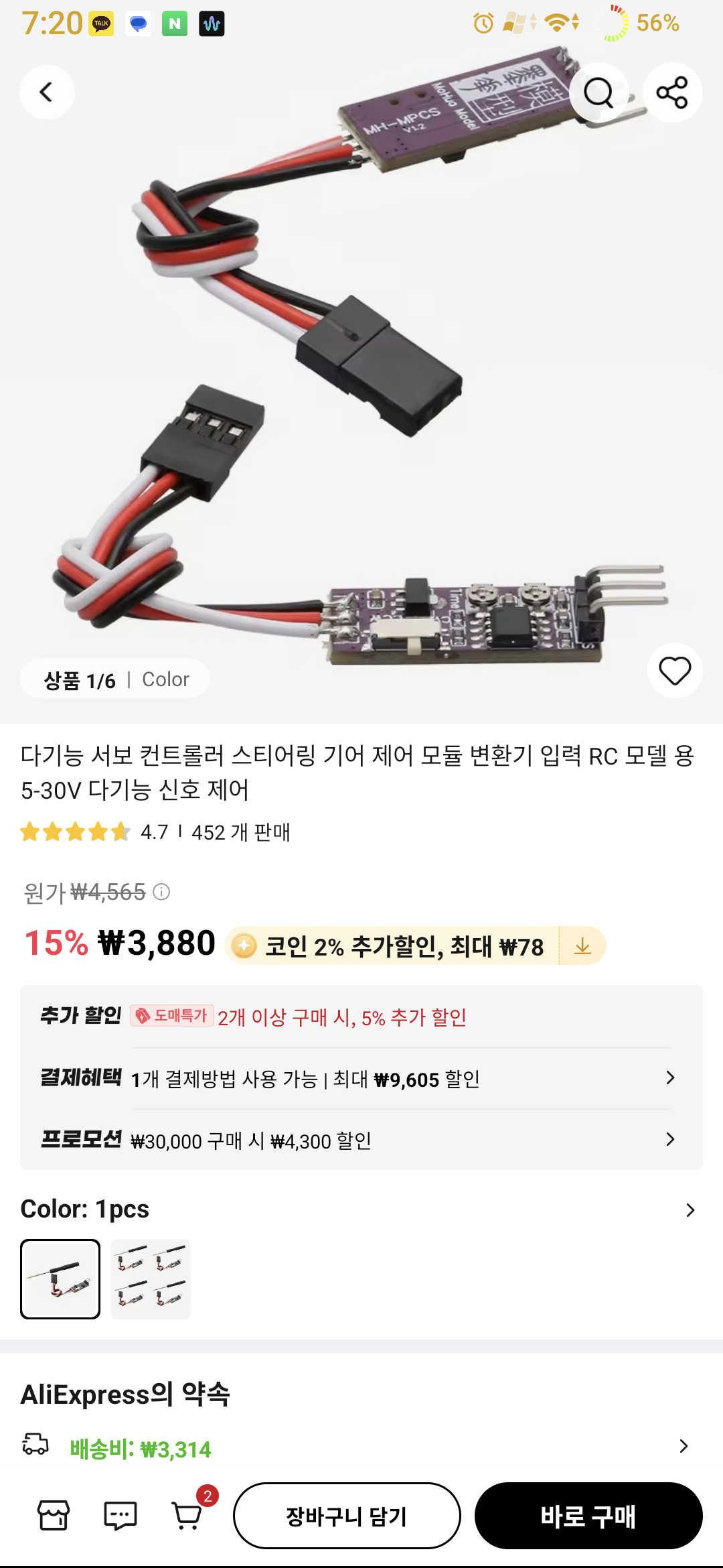
Finally, there is the servo angle limiter.
It is said that Gen.3 motherboards have a focus overshoot prevention feature that saves the corrected position in case of focus misalignment caused by reasons such as lamp replacement, and prevents operation beyond that position.
Unfortunately, Gen.3 motherboards are very expensive, and I have heard that their sensitivity to voltage is lower. (Reduced overclocking potential?)
Fortunately, since Maxa Beam uses the same servos used in RC, it is expected that by utilizing a circuit like a "servo angle trimmer" (or modifying the voltage divider circuit using the variable resistor inside the servo to allow hardware manipulation), it will be possible to hardware-adjust and correct the amount of focus overshoot that occurs when replacing lamps.
The battery build plan is the use 21700 6500mAh lithium-ion standard.
This high-energy-density 7S 4P lithium-ion battery, boasting a whopping 6500mAh capacity per single cell, is slightly lighter than the existing Maxa Beam Ni-Cd battery (estimated weight is just over 2kg).
However, calculations indicate it is sufficient to power a Maxa Beam overclocked to 120W for over 4 hours.
(If necessary, you could reduce the weight at the cost of slightly shorter usage time.)
Currently, the 21700 is the "technically most advanced standard cylindrical lithium battery." It has a higher energy density than the 18650.
The Maxa beam is excellent in every way and will be used alongside (or as a replacement for) the polarion I currently own in the future.
However, it is certain that there are a few points of dissatisfaction.
I have discovered numerous non-performance issues, such as the cooling design, room for weight reduction, low lumen values (in fact, the lumen figures are terrible... but the candela values are very good! - this is surmountable; I will elaborate on this in the main text below), reduced efficiency due to the use of older semiconductor components, and the thickness of the main power pattern on the PCB. I intend to modify these to suit my needs.
Caution: Maintenance by the headquarters (peakbeam systems) for this modified Maxa beam will likely be very limited.
Therefore, please "before the try this, and exercise caution and proceed with utmost care."
1. Back cap and control cables
->
The MBS 450 model has a total of two components blocking the rear: the "connector component for external control" and the "main power connector component."
However, to me, these components were completely useless.
First, the component for connecting the external control cable.
"Why is this necessary? I don't want to control this externally... :( Since it's not needed, I'll remove it without hesitation."
Twist the handle internal control cables neatly to organize them.
Second, the main power cable. In fact, the current capacity of the Maxa Beam's main power cable is likely significantly lower than that of the current 21century XT60. "I am removing the main power connector to install the XT60."
A word of caution: "You must keep the main power connector safe to have the flashlight serviced!!"
- According to the emails exchanged, they stated, "Modifying the main power connector is absolutely not recommended; without that connector, we cannot perform flashlight maintenance."
##### 1
We have secured two holes. Now, if we machine the circular center hole larger and slightly modify the square hole as well, we should be able to mount a 30x30mm cooling fan.
We anticipate that this will effectively resolve the heat generated by controlling the large current, given the characteristics of short-arc lamps where "low voltage and large current flow."
Furthermore, we expect this will help reduce power degradation caused by heat.
##### 2
I confirmed that supplying overvoltage (around 15V?) to the Maxa beam Gen.2 motherboard causes it to operate in "Lamp Overclock Mode."
Since this has been proven not only by me but also by a Maxa beam owner in Germany
(To summarize the story: "(He, like me, owns a 2nd generation model) One day, he accidentally input 30V into the Maxa Beam. It felt brighter than usual for some reason, but until then, he didn't realize that a whopping 30V was being supplied! Later, after replacing the lamp (which had exploded due to excessive overclocking), it surprisingly worked normally!")
and I have boldly decided to use the Maxa beam in an overclocked state at around 120W.
As this can also cause increased heat, it is expected that the additional forced air cooling system mentioned in ##### 1 will be necessary.
Change the "lamp power cable"
I determined that the standard lamp cable on the maxa beam is very rigid and inflexible, which could place excessive stress on the heated lamp. Additionally, the black color absorbs all light, potentially further reducing the maxa's already low lumen rating.
Consequently, I purchased "white silicone wire" and decided to solder it to the lamp connector. (I refer to the high-heat-resistant silicone wire commonly used in RC cars and drones.)
For soldering, regular solder must not be used. The heat generated by HID discharge lamps is beyond imagination.
I plan to use Mundorf's Silver-Gold Supreme solder. This solder contains nearly 10% pure silver, copper, and pure gold; it has excellent electrical conductivity but also a very high melting point (around 300 degrees Celsius? or higher?).
(Since both the solder and the wire are colors that reflect light well, I suspect that the temperature rise will not be high enough to cause the solder to melt and damage the connector.)
It is a really expensive and high-quality solder. In South Korea, standard solder costs about 4.5 USD, but the Mundorf Silver Gold Supreme solder being used in this project costs a whopping "500 USD (!!!!)" when calculated by weight—a completely insane price! Haha lol
Nowadays, high-efficiency, ultra-lightweight, compact regulators are being released that can directly replace the 7805 with a 1:1 standard.
##### 3
If you replace it with such a regulator, you can remove the heat sink mounted on the 7805 and significantly reduce weight and heat generation.
On the opposite side of the 7805, an IRF 640 FET and a Schottky diode are installed.
I am still looking for a replacement diode (original maxa beam diode is a 0.7V Vf one).
The IRF 640 is also a relic of the past. Its Rds-on reaches a whopping 0.1 ohms.
FETs released nowadays with the same voltage rating are being manufactured with Rds-on ratings in the 0.0x ohm range.
I purchased the IPP069N20NM6AKSA1 to replace the IRF 640.
Although the gate charge is higher, I believe it will not be a significant issue, contrary to expectations. (The details will be fully verified during the interim project review later on...)
Plan of battery.
As previously mentioned, Gen.2 motherboards can overclock the lamps by supplying an overvoltage of approximately 15V.
To overclock the lamps, a transformer circuit will be used to supply a constant voltage. Additionally, since this circuit features a constant current function, it is expected to prevent accidents such as the lamp power running wild.
Furthermore, this circuit is designed to accommodate a separate on/off switch, which prevents the worst-case scenario of the battery draining incessantly when the device is left idle.(generally, converter circuit is 15~30mA consumption during ready time.)
The circuit board is constructed using a Metal PCB, which offers a structure more advantageous for heat dissipation. Consequently, this means that changes in settings caused by heat can be prevented more effectively.
##### 4
To speak about the overclocking the maxa beam test results...
Some functions are not working properly. For example, this includes the strobe function, entering power saving(low bright) mode, a short warm-up time upon initial power-on, and high-output mode..
- To briefly discuss the cultural differences between the U.S. and Korea...
In the U.S., it is expected that the Maxa Beam is used in an environment where it can be "practically useful," such as for home defense.
For this reason, I believe users may prefer "certain functions necessary for security, patrol, and defense," such as the strobe function.
On the other hand, in Korea, such functions are practically unnecessary.
Except for people in the military, police, and fire departments...
For ordinary people like me, the strobe function is utterly useless—something we might use once every ten years just for fun, or maybe not at all.
If you need to send a signal over a long distance, I believe it is better to simply use the Maxa Beam's superior Spot Beam.
Therefore, I believe that securing a brighter lumen rating to increase practicality is the correct direction, at least in the flashlight usage environment in Korea, so I will keep it fixed in an overclocked state. -
- There is virtually no need for an initial warm-up time. Since it is already overclocked, extremely powerful power is supplied. -
However, since the focus adjustment works normally and can be locked into constant high-beam mode, I believe there is a merit in that you do not necessarily need to upgrade the motherboard to Gen.3.
(The practicality resulting from the improved lumen values is a bonus!)
Finally, there is the servo angle limiter.
It is said that Gen.3 motherboards have a focus overshoot prevention feature that saves the corrected position in case of focus misalignment caused by reasons such as lamp replacement, and prevents operation beyond that position.
Unfortunately, Gen.3 motherboards are very expensive, and I have heard that their sensitivity to voltage is lower. (Reduced overclocking potential?)
Fortunately, since Maxa Beam uses the same servos used in RC, it is expected that by utilizing a circuit like a "servo angle trimmer" (or modifying the voltage divider circuit using the variable resistor inside the servo to allow hardware manipulation), it will be possible to hardware-adjust and correct the amount of focus overshoot that occurs when replacing lamps.
The battery build plan is the use 21700 6500mAh lithium-ion standard.
This high-energy-density 7S 4P lithium-ion battery, boasting a whopping 6500mAh capacity per single cell, is slightly lighter than the existing Maxa Beam Ni-Cd battery (estimated weight is just over 2kg).
However, calculations indicate it is sufficient to power a Maxa Beam overclocked to 120W for over 4 hours.
(If necessary, you could reduce the weight at the cost of slightly shorter usage time.)
Currently, the 21700 is the "technically most advanced standard cylindrical lithium battery." It has a higher energy density than the 18650.
Last edited:


