• You must be a Supporting Member to participate in the Candle Power Forums Marketplace.

    You can become a Supporting Member.

Mateminco MT90vn+ = Farthest Reflector Thrower ...COMING SOON...

Alex1234

Flashlight Enthusiast
Joined
Jan 23, 2010
Messages
4,003
Location
Bear Delaware
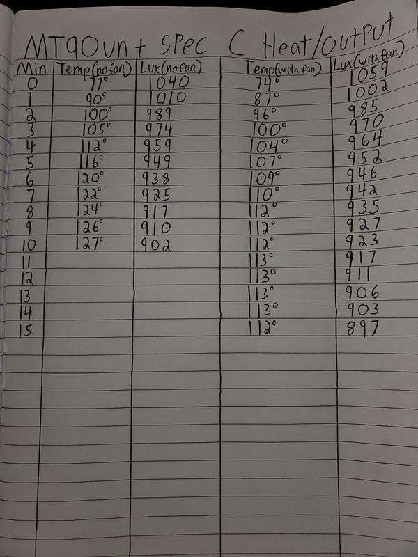
Did a heat test on the MT90VN+ Spec C Heat/Output test. with no fan the output drop between 1 and 10 minutes is 11%. With the fan the drop is only 7.5% and the light temp without the fan at the 10 minute mark was at 127 degrees F and 112F with the fan. With the fan the temp actually leveled out and hit equilibrium and actually started to fall at 15 minutes but at this point voltage was at 3.8V so the led was producing less heat. once i let the light cool down back to room temp i fired it up again and it was at 970 lux about 100 less then turn on so the batteries draining was also a factor in the output drop not just the heat. Overall I think this preforms incredible with maintaining output over time. Vinh did a awesome job with this one.


20200830_022724 by Alex Littig, on Flickr
 

Joe_torch

Newly Enlightened
Joined
Apr 14, 2008
Messages
145
Hi Alex,

Thanks for the information.:thumbsup:
This platform is so great, the performance justify the size and weight.
 

Skylumen

Newly Enlightened
Joined
Sep 14, 2010
Messages
0
I haev shipped 6 samples. 3 has been delivered. If you got your light then your light has Low Voltage Protection. If you have not gotten your light yet then your light will have Low Volatge Protection Delete. I have decided in this so this light can literally drain down the battery until the cells are dead and you can run Turbo without the light trying to step down because of voltage sag. This monster will be capable of really exacting every bit from the cells without needing to step down.
By the way just for kick you should run the light on just 1 cell to see the impressive performance just for fun.
 
Last edited:

Rasher

Enlightened
Joined
Sep 4, 2018
Messages
385
Location
Mostly California
...If you for your light then your light has Low Voltage Protection. If you have not gotten your light yet then your light will have Low Volatge Protection Delete. ...
Don't know if mine has or has not the delete - it showed up today. I sent you an e-mail re: missing cap for handle. Also, does the battery voltage indication in VNX2 mean anything on this light? I get 23 blinks when entering config mode, indicating 5.2v.
 

Skylumen

Newly Enlightened
Joined
Sep 14, 2010
Messages
0
Don't know if mine has or has not the delete - it showed up today. You got it the delete.
I sent you an e-mail re: missing cap for handle. The tail cap?

Also, does the battery voltage indication in VNX2 mean anything on this light? I am not sure after the LVP delete...

I get 23 blinks when entering config mode, indicating 5.2v.
 

Skylumen

Newly Enlightened
Joined
Sep 14, 2010
Messages
0
Hi Vinh, I have a stock MF05 (that I have not sent to you yet) and I am not planning on using the handle nor the fan. I can send you my handle fan battery cap, if you need.

One of my customer said his fan cap is missing but I didnt even mess with the handle at all. Maybe its around my house but I dont remember taking it out. Let me look first. THank you so much for your offer. Too generous!

If I cant find it I will gill you some store credit for the fan handle? :)
 
Joined
Dec 12, 2006
Messages
580
Location
Los Angeles, CA
I live near a concrete storm runoff, a straight stretch all the way down to a structure 880 yards away. I could not light it up, to my consternation. This evening I carried the Mateminco MT90vn+ to the wash and lo! I could visually see the very end get illuminated even with all the background light shining back!

This light tames 5,500 ANSI lumens into a straight-shot beam. Awesome!

lovecpf
 
Last edited:

Skylumen

Newly Enlightened
Joined
Sep 14, 2010
Messages
0
5500L is actually my guesstimate at 2S. Factory claim 7000 but I doubt it.
 

LuxLuthor

Flashaholic
Joined
Nov 5, 2005
Messages
10,654
Location
MS
Just got my MY90VN today and both battery carriers have dead shorts in them.

While waiting for Samsung 30Q 18650 3000mAh, I put in Panasonic NCR18650B fully charged cells and was in the process of taking a DMM reading from both ends which was 0 volts, while within 5 seconds I felt the cells getting warm.


I was careful to observe the -/+ markings on the end circuit boards, and got the same result from the other one.


I noticed the solder which appears to form a U shape and what appears to be scratched/gouged lines which you can see from these photos.

Also I'm not seeing how circuit is made from tailcap end of bottom battery carrier, as there is no contact spring in tailcap. I am assuming that the aluminum round spacer with soldered springs on both sides goes in between the two carriers.


Last edited:

Skylumen

Newly Enlightened
Joined
Sep 14, 2010
Messages
0
You do not follow the + or - signs. All negative to the springs. The carriers are modded.
And yes the plate with the dual spring goes in between the carriers.
 

LuxLuthor

Flashaholic
Joined
Nov 5, 2005
Messages
10,654
Location
MS
You do not follow the + or - signs. All negative to the springs. The carriers are modded.
And yes the plate with the dual spring goes in between the carriers.

First, some simple instructions would have been great on something that goes against a printed circuit board label of battery placement.

I tried that insertion first and got 0 voltage with my Fluke DMM contacting both ends of each carrier. So then when I looked at circuit board and saw the markings for +/- I assumed that was the proper way and got the dead short.

There is no answer for how a circuit is completed with no contact spring in tailcap or any other method of making contact with bottom terminal of carrier.

If you look at my posts and sig, I'm not a noob here.
 

Skylumen

Newly Enlightened
Joined
Sep 14, 2010
Messages
0
The tail cap doesn't need any spring. The stock light is the same way. Both positive and negative are on either side of the carrier.

All battery negative goes to spring. The two carriers sandwich the included plate with opposing springs.

If the light does not work this way the carriers have been shorted and likely need to be repaired.

Can someone please take a photo of how the cells should be installed? Sorry I dont have a sample in for photos.

I will add a note to state all battery negative go towards the spring in future shipment.
 

richbuff

Flashlight Enthusiast
Joined
Nov 21, 2014
Messages
2,264
Location
Prescott Az
The tail cap doesn't need any spring. The stock light is the same way. Both positive and negative are on either side of the carrier.

All battery negative goes to spring. The two carriers sandwich the included plate with opposing springs.

If the light does not work this way the carriers have been shorted and likely need to be repaired.

Can someone please take a photo of how the cells should be installed? Sorry I dont have a sample in for photos.

I will add a note to state all battery negative go towards the spring in future shipment.
 

Alex1234

Flashlight Enthusiast
Joined
Jan 23, 2010
Messages
4,003
Location
Bear Delaware
That is not the spec C battery carriers. This post is just going to make it more confusing. All 4 spings would be on the same end if it was the spec C.
 
Last edited:

Alex1234

Flashlight Enthusiast
Joined
Jan 23, 2010
Messages
4,003
Location
Bear Delaware
First, some simple instructions would have been great on something that goes against a printed circuit board label of battery placement.

I tried that insertion first and got 0 voltage with my Fluke DMM contacting both ends of each carrier. So then when I looked at circuit board and saw the markings for +/- I assumed that was the proper way and got the dead short.

There is no answer for how a circuit is completed with no contact spring in tailcap or any other method of making contact with bottom terminal of carrier.

If you look at my posts and sig, I'm not a noob here.

20200901_195101 by Alex Littig, on Flickr
20200901_195242 by Alex Littig, on Flickr
 

star_c_star

Enlightened
Joined
Feb 9, 2013
Messages
675
That is not the spec C battery carriers. This post is just going to make it more confusing. All 4 spings would be on the same end if it was the spec C.


Yes, that is true. I also have Spec C, and all four springs are on the same end of each carrier.

Luckily, I didn't look for positive or negative signs at the base of each battery holder. I looked for the spring being at the negative end, since I already knew that Vinh had modified the carriers.
 

LuxLuthor

Flashaholic
Joined
Nov 5, 2005
Messages
10,654
Location
MS
Ok, I finally resolved the issue with the battery carriers after seeing the photo that Alex posted. I was assuming the circuit was between both center positive contacts on top and bottom. Now I know the circuit is between the center contact and outside of end of carrier.


So I have 4.15V in each carrier, and have inserted them in light with middle dual spring disc. However no light comes on.


I tried reversing the battery carriers even though they have the same polarity orientation with + center and - outside end plate, still no light comes on.


I have tried fast click, series of fast clicks, and press and hold (all from off), never have had a light display.


I have inserted and removed carriers several times thinking that might reset the chip, but nothing has worked. It is like the light is locked off, or there is some internal short in driver board.


If you have no other suggestions, please let me know If I need to send it back to you to get fixed.
 
Top