Standlight and Martin's Circuit 12 help please!

Steve K

Flashlight Enthusiast
Joined
Jun 10, 2002
Messages
2,786
Location
Peoria, IL
Yip, the frequency is exactly the same before and after the fets. PLEASE PLEASE PLEASE tell me it should be double the freq after the FETs!

I think it should indicate twice the frequency. However, I'm not going to tear my light apart to verify this! :)

A scope should easily verify the frequency, and I think most meters could too, assuming that they are designed to measure frequency. The AC frequency of the dynamo should easily be within the range that it can handle (and you can check the manual to find out).

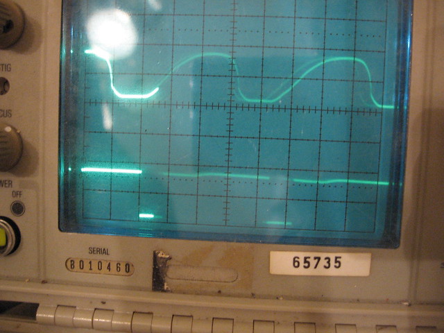
For reference and for the heck of it, here's a scope photo of the output of the rectifier in my circuit, and below it, the output of the first one-shot.....

5368156041_cc2392aeb4_z_d.jpg


wasn't there a problem with your mosfet bridge rectifier before? Or am I thinking of something else?
 

piesoup

Newly Enlightened
Joined
Oct 31, 2008
Messages
114
Location
East Anglia
I'm certain it's the bridge that's causing problems. I found two errors on my schematic from when I copied it from yours. Q2 and Q4 have their drain and sources the wrong way around! As soon as I've bathed the kid, I'll be out in the garage! I'll let you know!

Regarding the voltages, my Meyer was trying to measure the RMS voltage, it's not tried AC or DC so I don't think it is there best tool for the job. But it can measure frequency...
 

Steve K

Flashlight Enthusiast
Joined
Jun 10, 2002
Messages
2,786
Location
Peoria, IL
It works!!!!!!!!!!!!!!!!! :twothumbs

outstanding!

Nice that it could be found without tearing things up too much. Keeping the drains and sources all correct gets tricky when trying to remember which one is a P mosfet and which is a N. I recall spending extra time when wiring mine up, making sure that stuff was really connected to the right stuff. Things are so much simpler when dealing with just the schematic. :)
 

piesoup

Newly Enlightened
Joined
Oct 31, 2008
Messages
114
Location
East Anglia
Thanks! I'm chuffed I found the error.

Reading about the RC circuits on the one-shots got me thinking about the frequency. So I measured it at the wheel and the LEDs. Then I remembered the calculation for period and frequency. The RC circuit's 'timer' was nowhere near the 31Hz I was measuring. The only parts that can affect the frequency are the FETs in the bridge. I found your original schematic on Flickr and used that to find errors in my schematics. When I copied yours into the online PCB program, I messed up the drain and source of two of the FETs. When it worked the first time around, I think I only had one FET the wrong war around, the other was correct by accident, hence the flickering and the high speed LEDs did turn on, albeit at 20mph+.

Now, no flicker, the light is really smooth, even at relatively sedate speeds. The high speed LEDs turn on at just over 11mph, perfect!
Now the hard part, getting it mounted and tidying up all the cables.

I will update with pics once I have the printed pcb housing and the light housing mounted.

Thanks again Steve for all your help. I really appreciate it.
 

Steve K

Flashlight Enthusiast
Joined
Jun 10, 2002
Messages
2,786
Location
Peoria, IL
glad that the story has a happy ending!

Now you know why practicing engineers are so detail oriented... there are a million ways to put stuff together wrong, and only one way to do it right!
 

piesoup

Newly Enlightened
Joined
Oct 31, 2008
Messages
114
Location
East Anglia


Finished!!

Steve, thank you so much for your advice and patience! I have learned a hell of a lot from doing this project. When it's fitted to the bike with all my touring kit I'll post up more pics.
Next project is to finish the USB / battery charging system then sew all my frame bags. Always gotto have something on the go!
 

Steve K

Flashlight Enthusiast
Joined
Jun 10, 2002
Messages
2,786
Location
Peoria, IL
Very nice!

It's always rewarding to see a project on the verge of being wrapped up! Sometimes it's a bit traumatic to think of all of the challenges and hair-pulling required to get to the finish.... but it certainly builds skills and teaches you to not panic when trouble strikes.

.. that reminds me... I'm in the middle of fixing a Supernova Triple headlight for an acquaintance. Lots of dead parts and damage, but the circuit wasn't too complicated and could be reverse-engineered. I'll have to start a thread about it and share the fun with everyone else. I've got new parts on order right now. I like to think that it should be easy to replace parts and get it back together and operational, but I'm hesitant to "count those chickens before they hatch". :)
 
Top