Re: Will this circuit work?
I see that this stuff is old hat for you guys")
Looking back, bandgap also mentioned doing dynamo charged batteries for years in a thread that Martin started on Charging Li-Ion with ripple current.
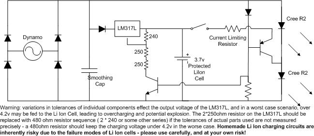
What I was wondering is, if we took advantage of the LM317L and protected li-ion batteries instead of supercaps, could we dispense with the zetex and use a circuit like this?

If I understand the LM317L resistors, the 500 and 240 ohm resistors should set a nominal max charging voltage of about 3.9V (with a worse case of 4.3V if the parts are out of spec enough) which is a voltage that provides a long lifetime on the li ion batteries, and the protection circuit on the li ion cell would prevent over discharge (or is that only for too much current draw and not deep discharge?). Add in a current limiting resistor on the output so that we keep the discharge within a reasonable range, and then a transistor switch and manual switch to only discharge when the bike is stopped and the switch set to "on".
Is this too simplistic again? I didn't see the LM317L mentioned in any battery charging threads, so I'm just guessing what works and what doesn't. Is 100ma too low of a current for charging a li ion battery? Or is this a viable solution for a "standlight" that can actually last for a while?
Or do you basically need a version of Alex latest circuit but with the components to activate the shutdown pin on the zxsc310 and maybe the switching transistor across the feed to the bottom cree?
In essence, Alex's circuit is ending up being very similar to mine. Here's the schematic for my first front standlight...
[ snip ]
You'll note that I use a switch to disable the standlight when the bike is parked. It's not desireable to fully discharge the nicad.
I see that this stuff is old hat for you guys
Looking back, bandgap also mentioned doing dynamo charged batteries for years in a thread that Martin started on Charging Li-Ion with ripple current.
What I was wondering is, if we took advantage of the LM317L and protected li-ion batteries instead of supercaps, could we dispense with the zetex and use a circuit like this?
If I understand the LM317L resistors, the 500 and 240 ohm resistors should set a nominal max charging voltage of about 3.9V (with a worse case of 4.3V if the parts are out of spec enough) which is a voltage that provides a long lifetime on the li ion batteries, and the protection circuit on the li ion cell would prevent over discharge (or is that only for too much current draw and not deep discharge?). Add in a current limiting resistor on the output so that we keep the discharge within a reasonable range, and then a transistor switch and manual switch to only discharge when the bike is stopped and the switch set to "on".
Is this too simplistic again? I didn't see the LM317L mentioned in any battery charging threads, so I'm just guessing what works and what doesn't. Is 100ma too low of a current for charging a li ion battery? Or is this a viable solution for a "standlight" that can actually last for a while?
Or do you basically need a version of Alex latest circuit but with the components to activate the shutdown pin on the zxsc310 and maybe the switching transistor across the feed to the bottom cree?
Last edited: