Steve K
Flashlight Enthusiast
An opportunity came up to help a friend who had a malfunctioning dynamo taillight on his hands. The story was that the standlight wasn't working. My guess was that the supercap might have been overstressed or possibly fatigued its leads. I asked him to see if he could open it up and take a few photos of the circuit board, just to get an idea of the damage or the cause of the failure. Also, it was a way to find out if it could even be opened up without destroying the light!
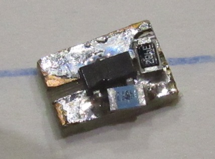
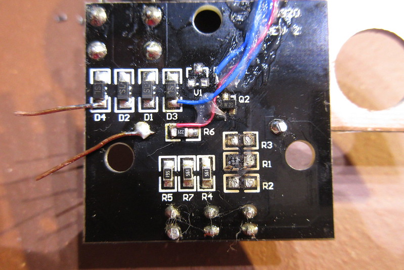
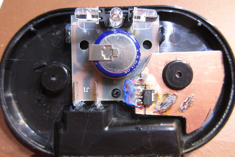
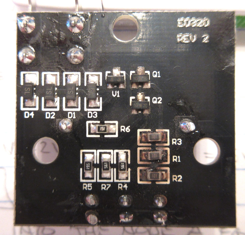
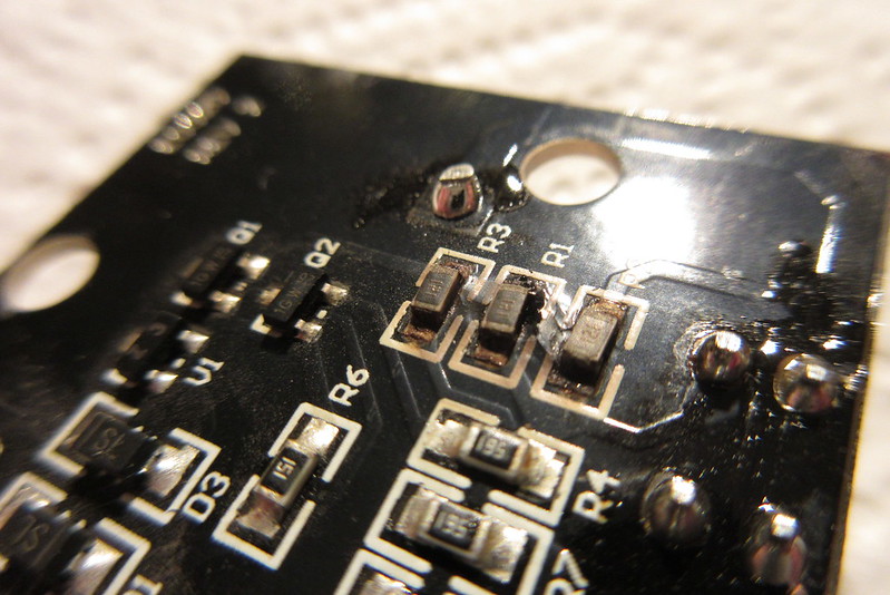
The photos showed three 0805 surface mount resistors that were quite brown and toasty, with some damage to the nearby portion of the circuit board. It didn't look too horrible. Seemed like it could be repaired, so I asked him to send it to me.
here are the photos that he sent.....
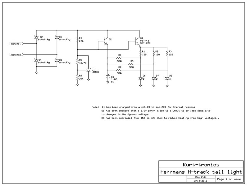
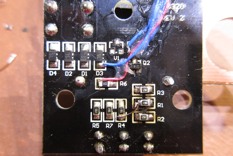
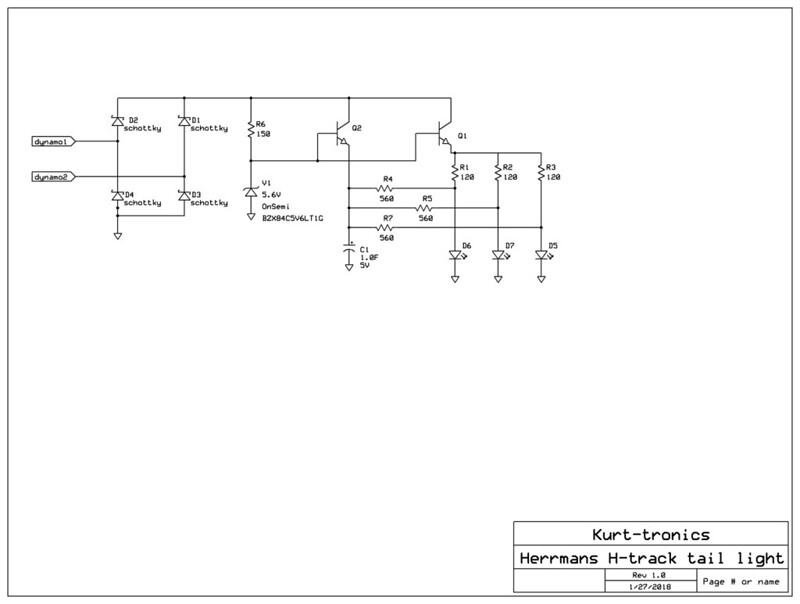
While waiting for it, I sketched out a schematic of what I thought the circuit might be. The three 120 ohm resistors (marked "121") suggested that one was in series with each LED to limit the current. The three 560 ohm resistors (marked "561") seemed like they would be used in series with the LEDs when the supercap discharged, providing the standlight function. U1 was a three terminal device. My guess was that it was a zener diode, with R6 being a series resistor. The zener voltage would then be fed into the base of a npn transistor, whose collector would be connected to the rectified dynamo voltage, and the emitter would be connected to the supercap. Basically, it was just a zener diode with the transistor acting as a current amplifier.
The Initial Inspection
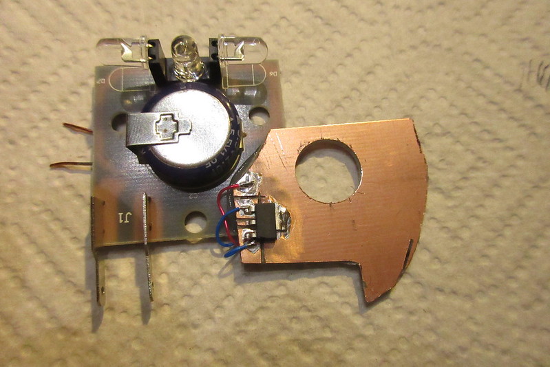
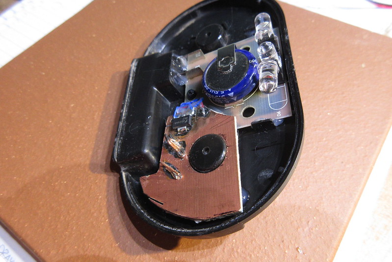
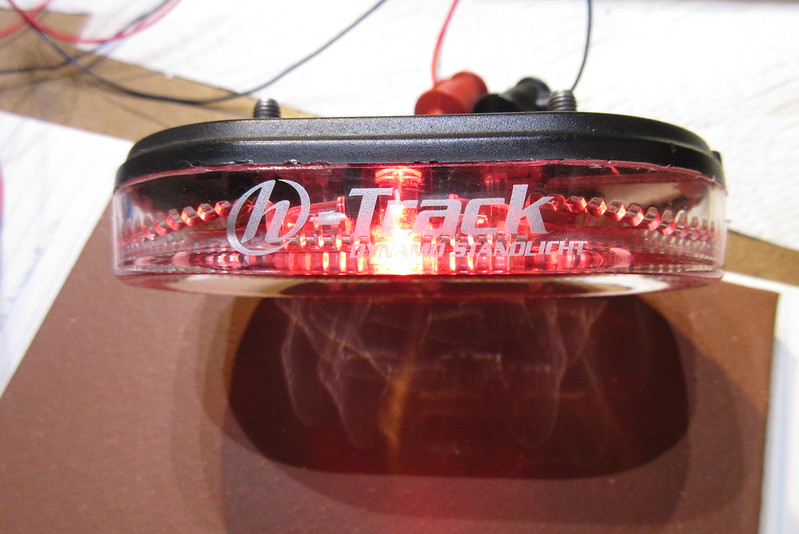
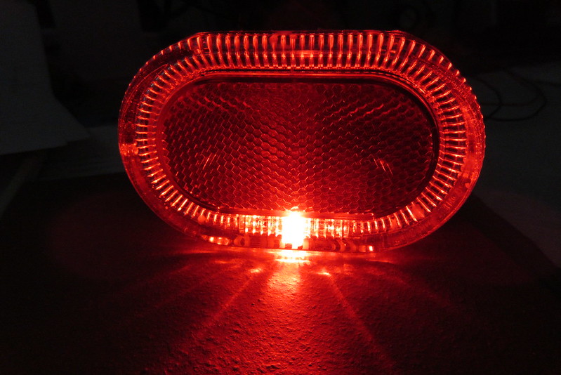
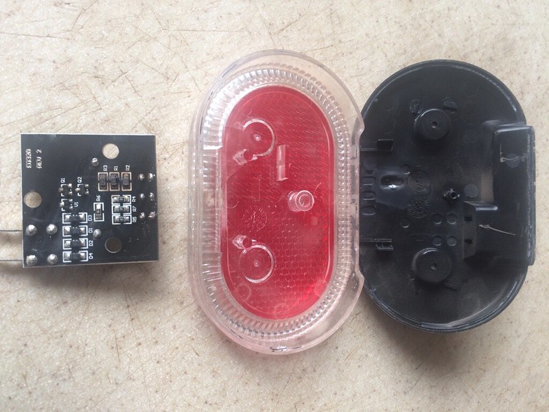
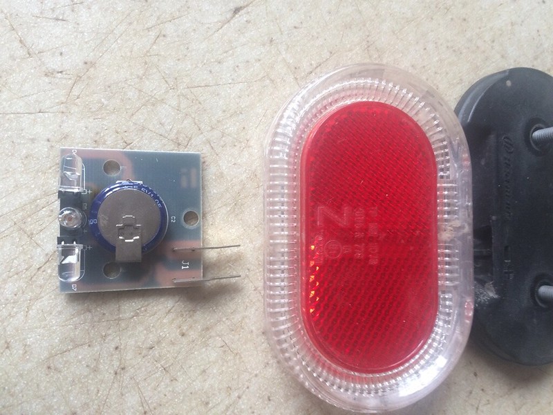
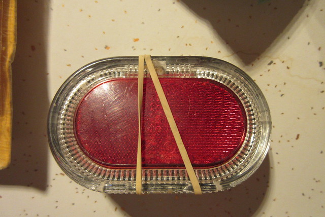
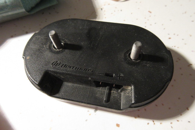
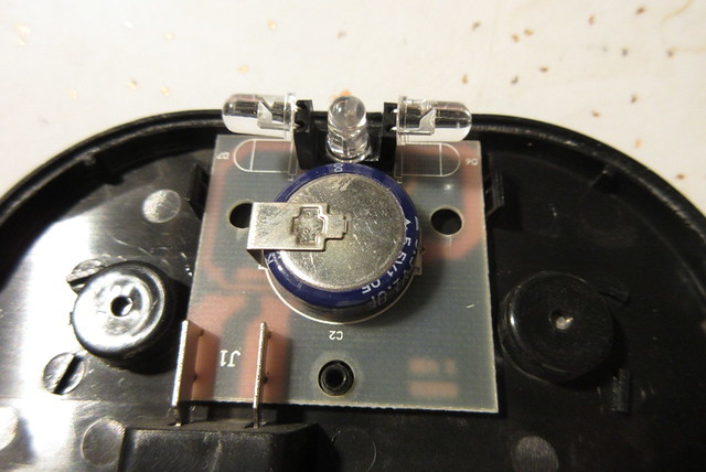
After a handful of days, a small package appeared in my mailbox. Inside was a Herrman's "h-track dynamo standlicht". This is a fairly low profile taillight designed to fit to two holes spaced 50mm, typically on a rear rack. The light has 3 LEDs, one of which is aimed to the rear. The other two feed into a light pipe (i.e. clear plastic channel) that spreads light around the circumference of the light, making it visible from all directions.
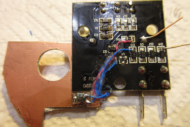
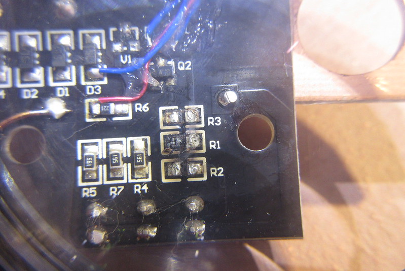
A look at the board (which lifts right out of the housing) only shows the damage that the early photos showed; R1, R2 and R3 were browned rather badly. (see photo below)
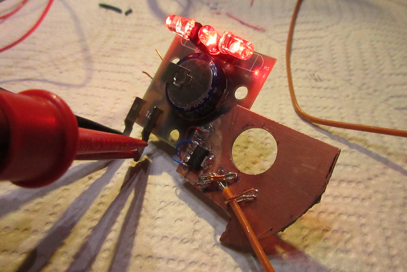
One big concern was whether the supercap was good. A visual inspection didn't show any bulging, which was good. No signs of broken leads on the supercap either (also good).
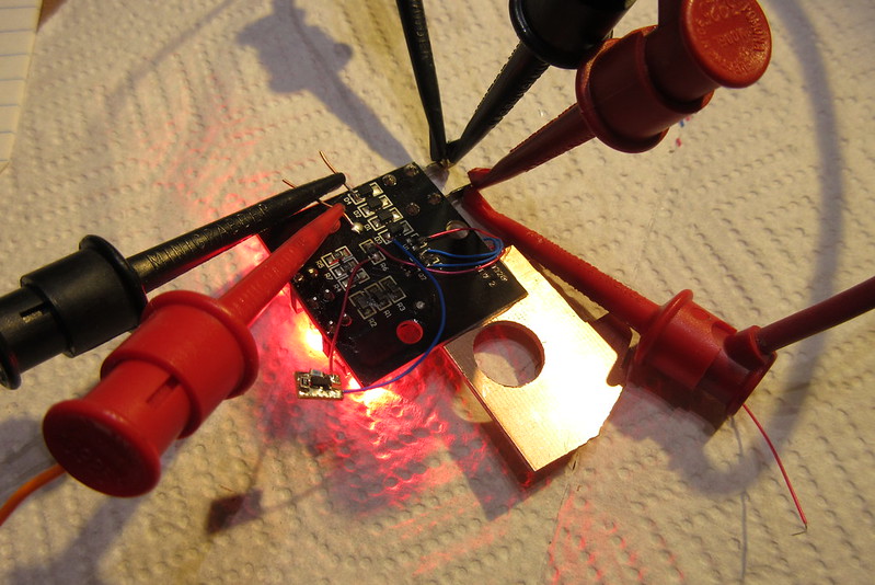
The board turned out to be single sided; i.e. it only had traces on one side. This is the least expensive way to make a board, and it makes it much easier to reverse engineer. A close look at the board reveals most of the traces. A multimeter lets you find the rest of the connections, especially those circuit traces that run underneath the components or are rather narrow and hard to see.
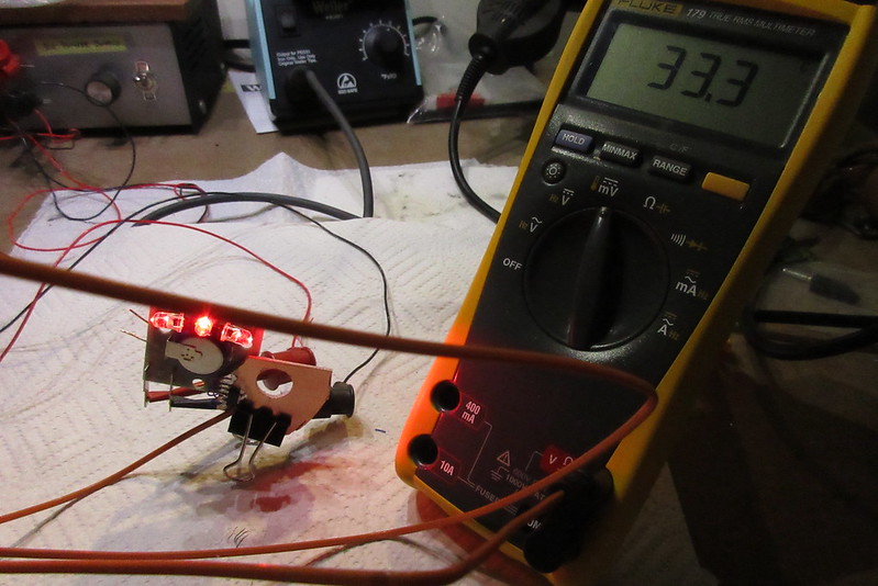
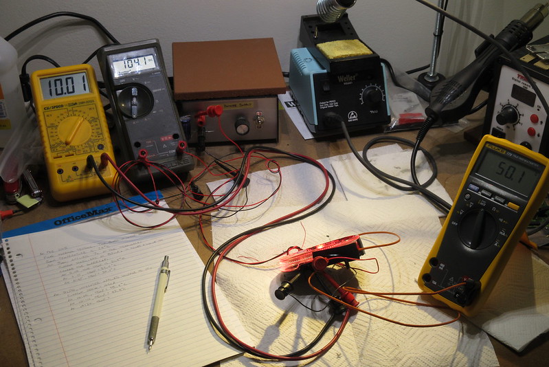
When the board had been checked and corrections made to my initial guess at the schematic, the only real place that I was wrong was about the two transistors. I had assumed that the two were used in parallel to charge the supercap. Instead, one transistor was used to provide a fairly steady 5V to each string of 120 ohm resistor and LED. Not a bad way to design it.
(come back tomorrow-ish for the next installment in this exciting/interesting/tedious tale of technology!)
The photos showed three 0805 surface mount resistors that were quite brown and toasty, with some damage to the nearby portion of the circuit board. It didn't look too horrible. Seemed like it could be repaired, so I asked him to send it to me.
here are the photos that he sent.....
While waiting for it, I sketched out a schematic of what I thought the circuit might be. The three 120 ohm resistors (marked "121") suggested that one was in series with each LED to limit the current. The three 560 ohm resistors (marked "561") seemed like they would be used in series with the LEDs when the supercap discharged, providing the standlight function. U1 was a three terminal device. My guess was that it was a zener diode, with R6 being a series resistor. The zener voltage would then be fed into the base of a npn transistor, whose collector would be connected to the rectified dynamo voltage, and the emitter would be connected to the supercap. Basically, it was just a zener diode with the transistor acting as a current amplifier.
The Initial Inspection
After a handful of days, a small package appeared in my mailbox. Inside was a Herrman's "h-track dynamo standlicht". This is a fairly low profile taillight designed to fit to two holes spaced 50mm, typically on a rear rack. The light has 3 LEDs, one of which is aimed to the rear. The other two feed into a light pipe (i.e. clear plastic channel) that spreads light around the circumference of the light, making it visible from all directions.
A look at the board (which lifts right out of the housing) only shows the damage that the early photos showed; R1, R2 and R3 were browned rather badly. (see photo below)
One big concern was whether the supercap was good. A visual inspection didn't show any bulging, which was good. No signs of broken leads on the supercap either (also good).
The board turned out to be single sided; i.e. it only had traces on one side. This is the least expensive way to make a board, and it makes it much easier to reverse engineer. A close look at the board reveals most of the traces. A multimeter lets you find the rest of the connections, especially those circuit traces that run underneath the components or are rather narrow and hard to see.
When the board had been checked and corrections made to my initial guess at the schematic, the only real place that I was wrong was about the two transistors. I had assumed that the two were used in parallel to charge the supercap. Instead, one transistor was used to provide a fairly steady 5V to each string of 120 ohm resistor and LED. Not a bad way to design it.
(come back tomorrow-ish for the next installment in this exciting/interesting/tedious tale of technology!)