HDS Systems #23

Candle Power Forums

Help Support Candle Power:

Best advice I've heard when receiving a brand new flashlight is to tip it straight out of the package and onto the floor. Then you can get on with the business of happily using it without worrying about the first drop and scuff.

That said, I do understand the current argument that HDS is charging premium prices for their lights, so it is not unreasonable to expect a premium product, although I suppose the definition of "premium" is wholly subjective. Apart from price, I think the biggest downside of the Rotary is a lack of user serviceability, but it is an excellent flashlight in every other respect.
 
I don't think it's a downside, I service my rotary tails perfectly and will not depend on sending it back for a simple rubber boot replacement. I have spare original o-rings, teflon line and lube. It's easier than it looks.
 
Based on what I've seen of Rotary disassemblies, removing the tail cap is not something I would rate as easy or convenient.
 
It might not be convenient, but it's easy if you're determined to do it and have minimal hand skills. Some videos make it more complicated and scary than it actually is.
 
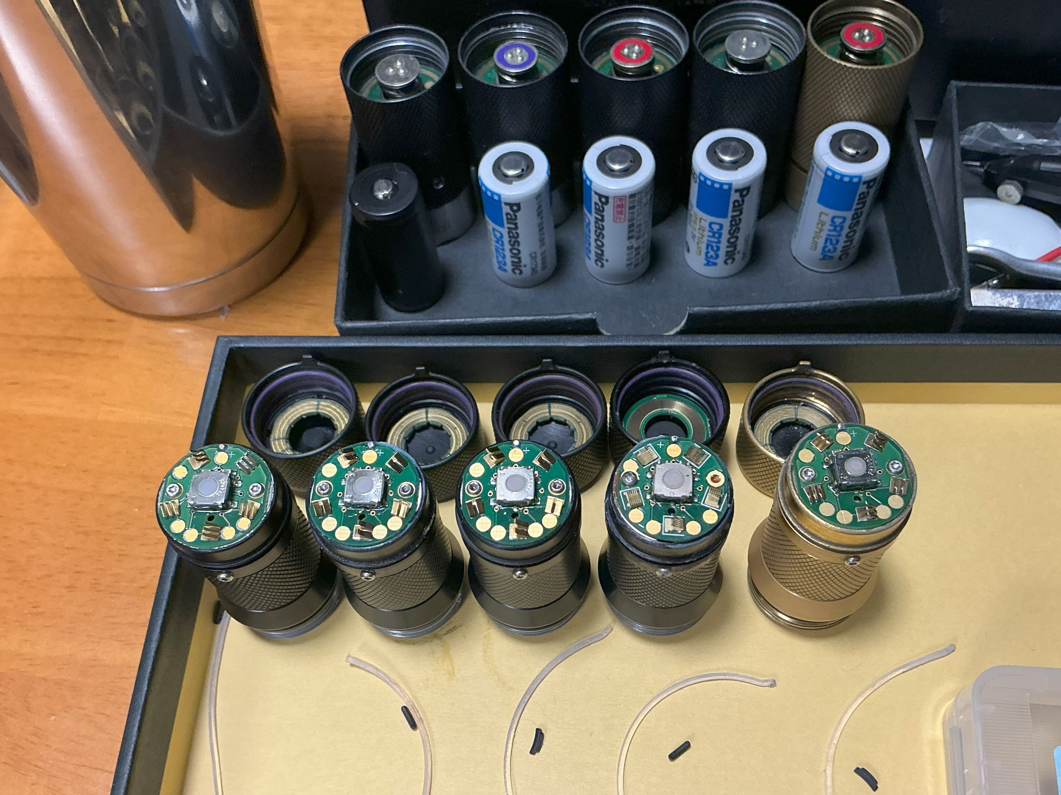
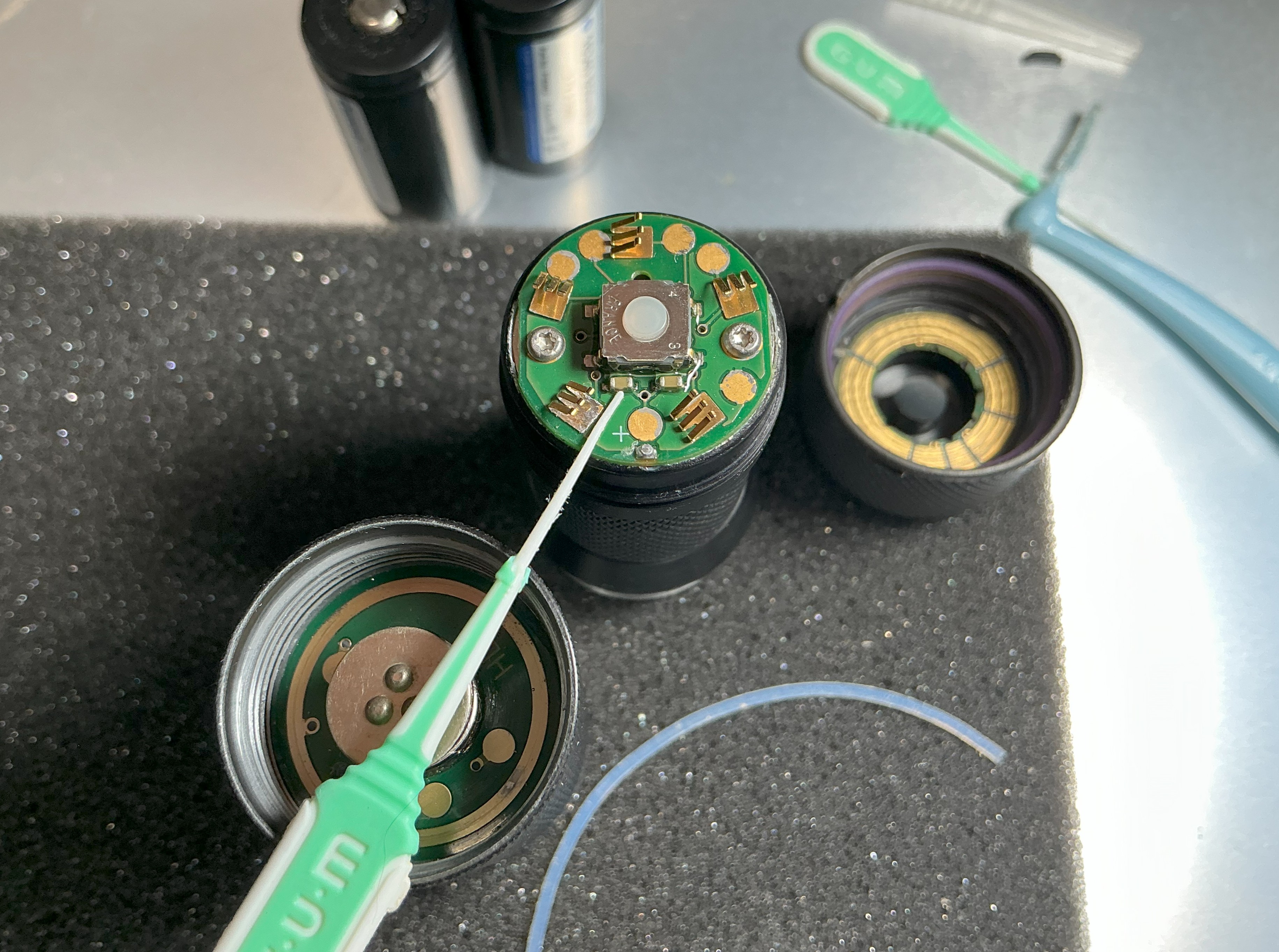
Disassembling the tail cap is easy once you get used to it, but it is still more difficult than a clicky cap, which can be opened simply by turning a screw. This image was taken while investigating the cause of the battery compartment not recognizing the CR123A.
1IMG_0662.jpg
 
@muichimon
Maybe it makes sense to explain (with pictures) to show how to remove the "black cap" and also on how to get finally a piece of the "plastic wire" with pliers or tweezers.

From my side I have not checked it out. But it seems the tricky point is "grabbing" the plastic wire.
 
As an Amazon Associate we earn from qualifying purchases. Product prices and availability are accurate as of the date/time indicated and are subject to change.
Oh, finally I was able to log in to the site again. Some strange error was preventing me from logging in, even though I saw and read everything

I'm looking forward to the new lantern. It will definitely be amazing! As for prices, I understand everything, this is the reality, when products and services jump by 50-100%, then the jump for a very good flashlight is not that big

Disassembling the tail cap is easy once you get used to it, but it is still more difficult than a clicky cap, which can be opened simply by turning a screw. This image was taken while investigating the cause of the battery compartment not recognizing the CR123A.
The photo of the insides is very interesting, thank you! :)
 
Later this year maybe?
Yes later this year.... Henry years, or Henry 3 weeks :D (sorry couldn't resist). Btw. the last Henry 3 weeks took almost 9 years when I was asking Henry for a new Ti light. :P

To be sincere, I am not expecting any new light anymore. For me the Rotary is almost perfect. The dual use capability of a single AA (Alkaline maybe NiMH) and CR123 / 16340 would be nice.
And even if the new light will come what would it cost? $500 ...? More ...? When I see the price increase over the last decade I see that I definately earn less money in compare to the price increase of the HDS lights.
And no I am not complaining. I am counting myself to the minority of people that are far away from poor.
 
Last edited:
This image was taken while investigating the cause of the battery compartment not recognizing the CR123A.
great photo, I hope you solved the battery detection

the manual says:
"if you have been using rechargeable Lithium-ion batteries and want to return to using regular (non-rechargeable) batteries, you must perform a reset. The simplest way to perform a reset is to turn on your flashlight (with the button released) and open the battery compartment until your flashlight turns off and then replace the battery compartment. If you fail to perform a reset when returning to using non-rechargeable batteries, your flashlight will act as if the new non-rechargeable battery needs replacing – just do a reset to restore normal operation."

unrelated:
71402-a1bb26731d85d3eb0b1f267cab9f3112.jpg
 
@muichimon
Maybe it makes sense to explain (with pictures) to show how to remove the "black cap" and also on how to get finally a piece of the "plastic wire" with pliers or tweezers.

From my side I have not checked it out. But it seems the tricky point is "grabbing" the plastic wire.
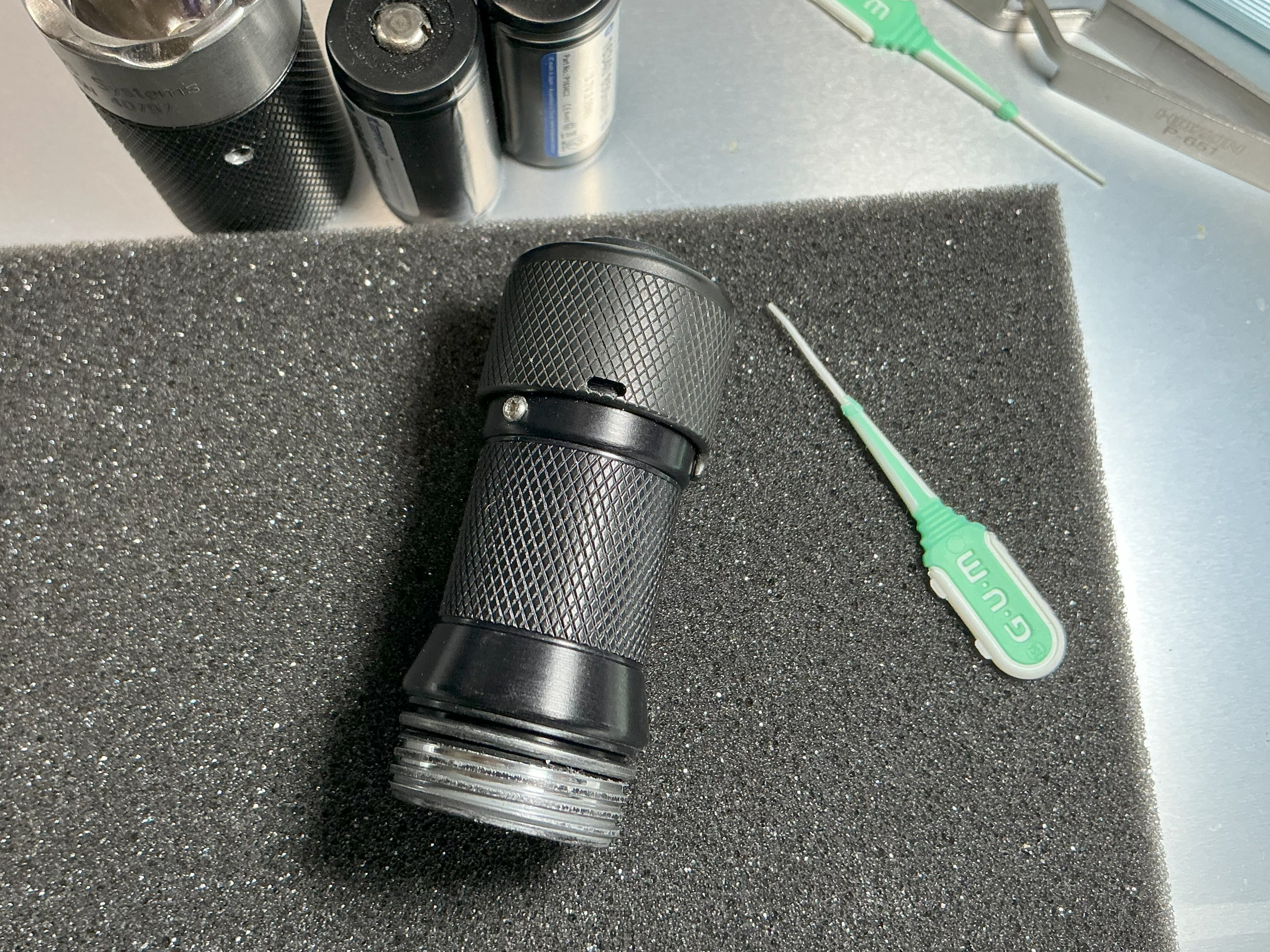
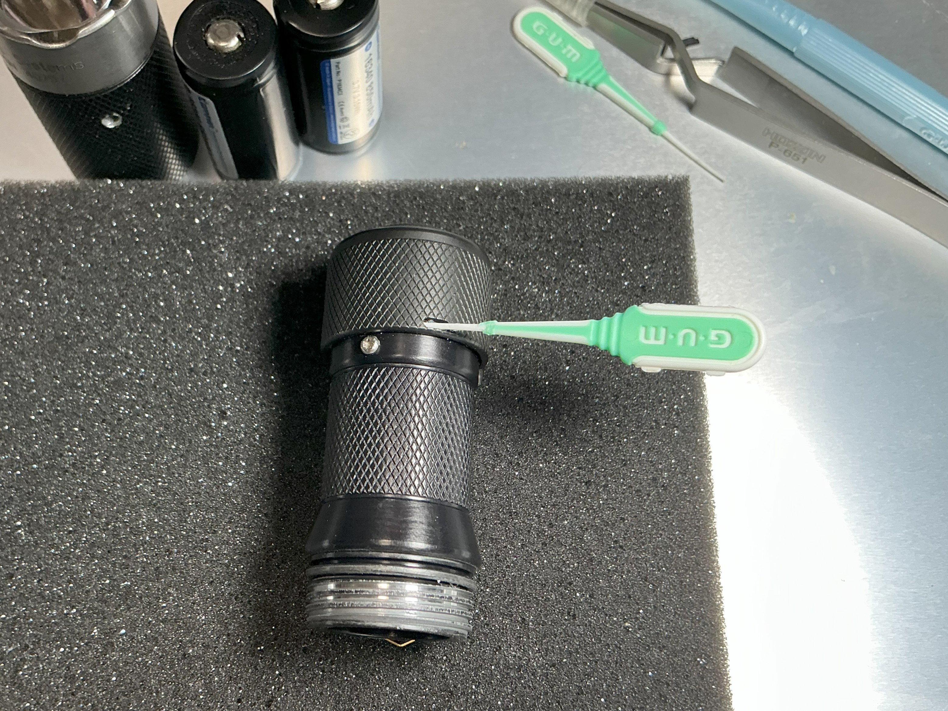
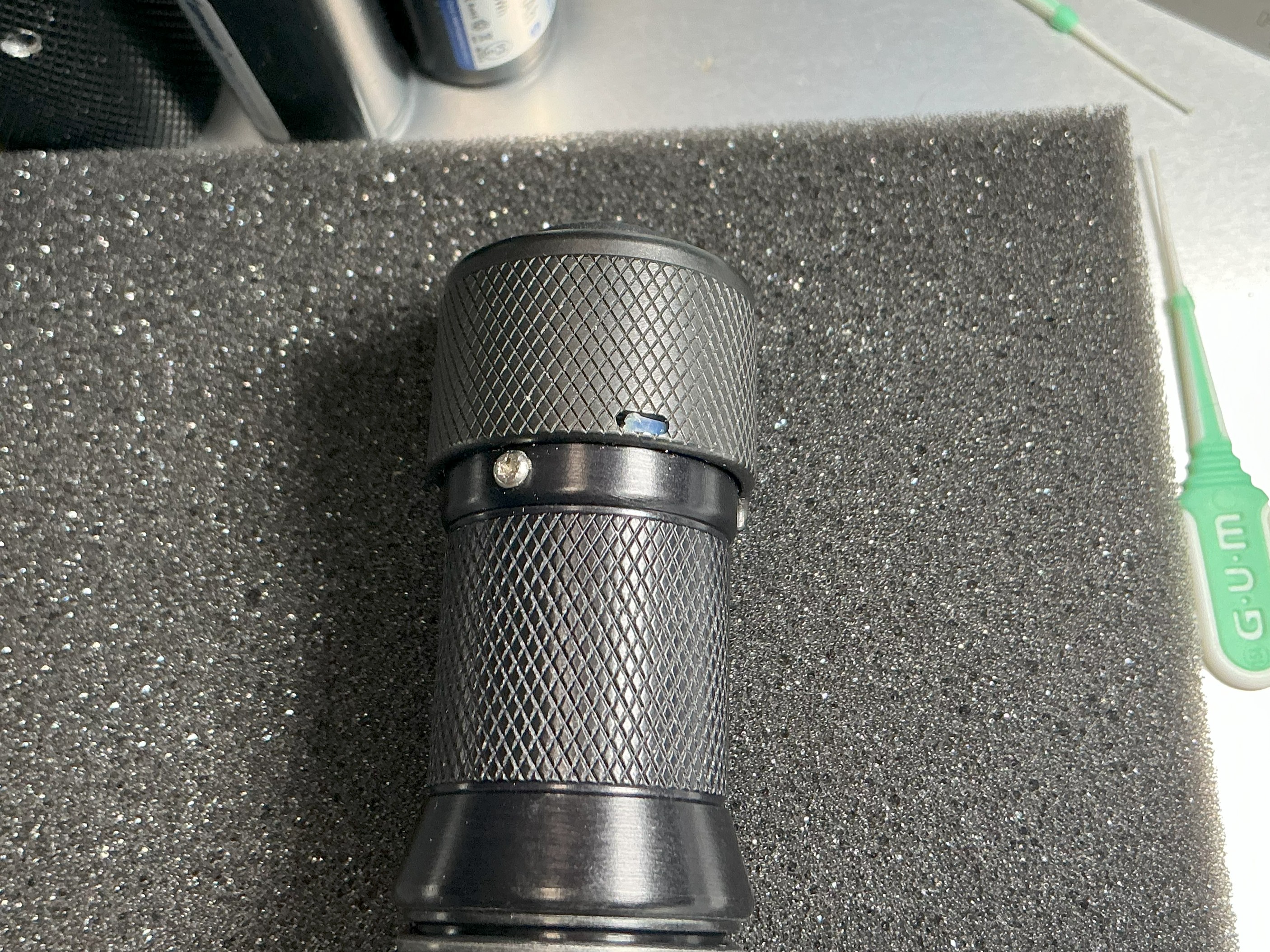
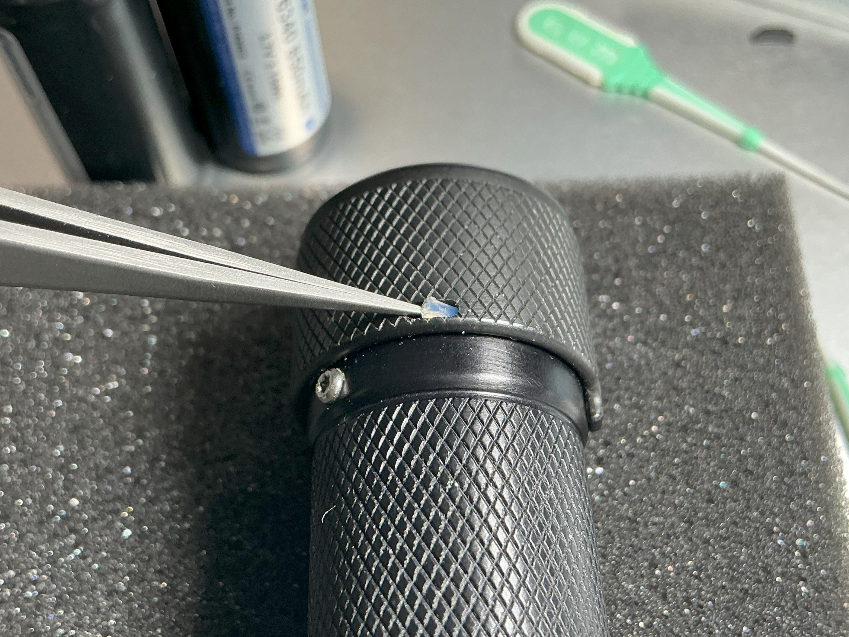
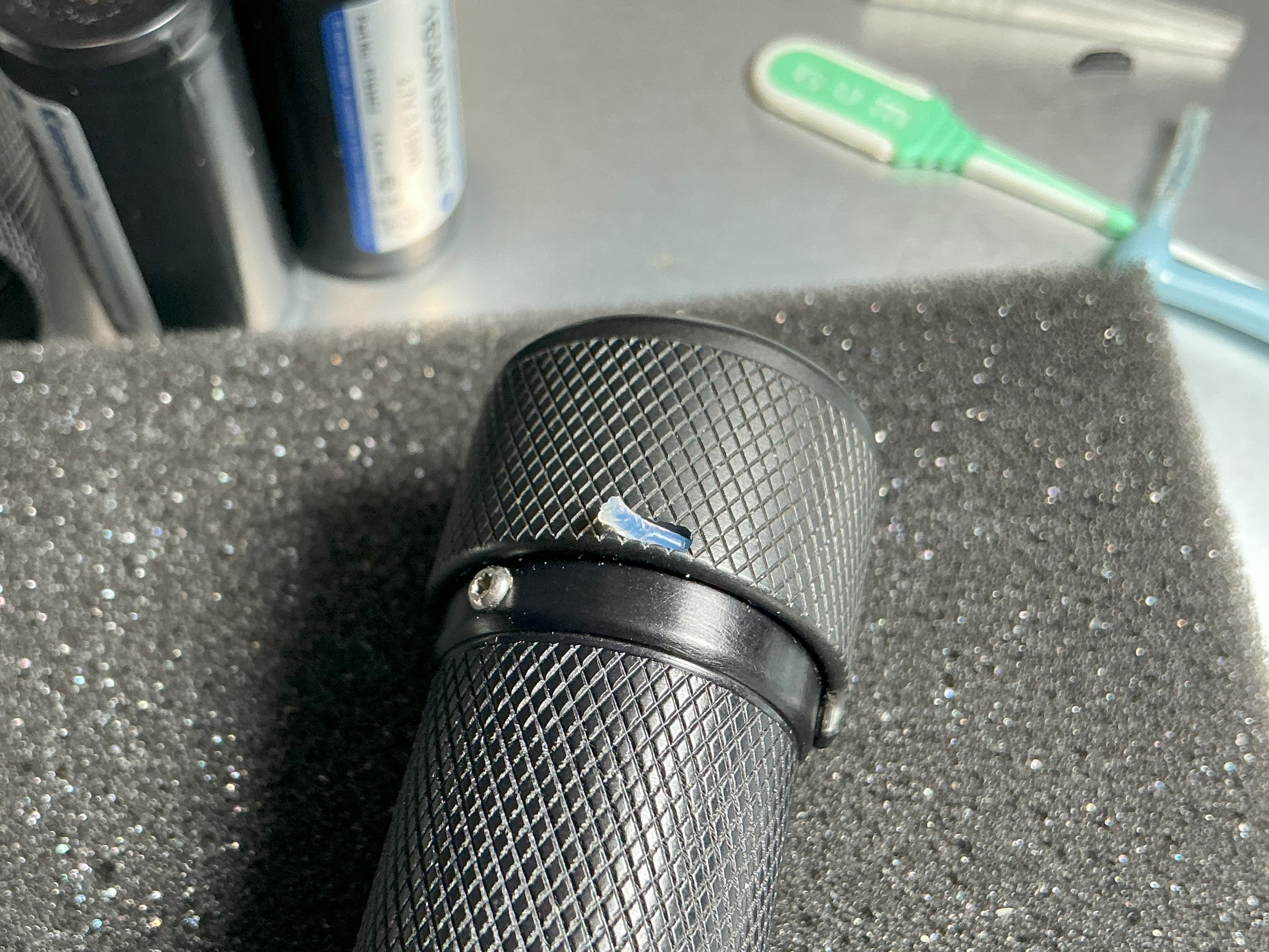
Here are the steps for disassembling the rotary cap.
1. Prepare a thin, flexible pick and a pair of tweezers with a fine tip. I use an interdental brush. Lift the rubber cap with the tweezers and insert the pick into the hole.
2. When you see the tip of the retaining wire pushed out by the pick, slide the tweezers under the wire and lift it up.
3. Gently pinch the wire with your fingertips and pull it out to remove the cap. Using tweezers or pliers to grip the wire too tightly can crush the tip, so pinching it with your fingertips is sufficient.
The time required for these steps is less than 30 seconds.

11IMG_0951.jpg
22IMG_0952.jpg
33IMG_0953.jpg
44IMG_0954.jpg
55IMG_0955.jpg
 
great photo, I hope you solved the battery detection

the manual says:
"if you have been using rechargeable Lithium-ion batteries and want to return to using regular (non-rechargeable) batteries, you must perform a reset. The simplest way to perform a reset is to turn on your flashlight (with the button released) and open the battery compartment until your flashlight turns off and then replace the battery compartment. If you fail to perform a reset when returning to using non-rechargeable batteries, your flashlight will act as if the new non-rechargeable battery needs replacing – just do a reset to restore normal operation."

unrelated:
View attachment 83093
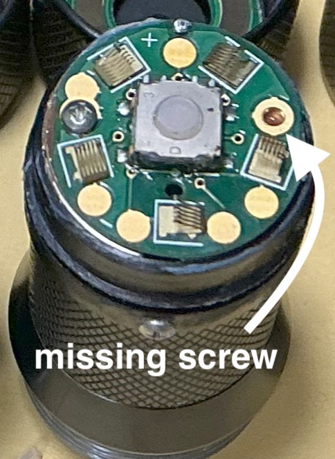
We suspect that the cause is a faulty chip resistor on the switchboard. In a normal battery compartment, the resistance values of each contact point are all the same, but in the faulty one, there are many areas with very low resistance values.
We are currently investigating replacements for these two chip resistors. We have the necessary soldering tools and plan to repair it.
66IMG_0957.jpg
 
We suspect that the cause is a faulty chip resistor on the switchboard. In a normal battery compartment, the resistance values of each contact point are all the same, but in the faulty one, there are many areas with very low resistance values.
We are currently investigating replacements for these two chip resistors. We have the necessary soldering tools and plan to repair it.View attachment 83324
Those 2 SMT parts look like capacitors, not resistors...
Unless you are referring to parts on the back side of the PCB and not the 2 next to the switch?
 
We suspect that the cause is a faulty chip resistor on the switchboard. In a normal battery compartment, the resistance values of each contact point are all the same, but in the faulty one, there are many areas with very low resistance values.
We are currently investigating replacements for these two chip resistors. We have the necessary soldering tools and plan to repair it.[ATTACH type="full"
On the picture you see as LEDphile already stated two capacitors. The resistors should be at the bottom of the board (your picture shows the top layer of the board).

In general it may (I am not say it must or it is!) possible that one or both capacitors are faulty. In my life of an electronics engineer I had it once in a while that such SMD capacitors were faulty and had a low resistance.
But anyway it may also the case the problem is related to a bad resistor.....

Also thanks a lot with this very valuable how to disassemble the rotary tail. (y) (y) (y) (y) (y) (y) (y) (y) (y)
(IMO this post valuable to get an own topic related to disassembling the tailcap. It would be easier to find for the future in compare to a post somewhere in the "generic" HDS thread.)
 
Was this small part a capacitor rather than a resistor? I'm glad I asked for advice before mistakenly purchasing the wrong part. I haven't checked the back of the switchboard yet, but to remove the board, I need to remove the solder from the signal lines. It seems that I can remove it by straightening the signal lines, but bending and stretching them repeatedly may cause them to break.
 
The two parts on the picture you are pointing at with the "GUM tool" are capacitors.

Here some information about SMD capacitors: https://www.zxcompo.com/understanding-smd-capacitors-and-smd-ceramic-capacitors-all-key-information/

On that linked page some examples of SMD capacitors
SMD-Multilayer-Ceramic-Capacitors.webp

At least mostly ceramic capacitors does not have printed the value on it. Resistors have this mostly directly or with colored rings.

Here an example of resistors (recangle and round)
SMD-Resistor-Sizes-SMD-Resistor-Package-Sizes-Chart.png


51aJMIEBnBL._AC_SX679_.jpg


SMD parts are somehow not easy due to the fact they are very small. If you are extremely small than you only have very small parts with nothing on in. At least I am not able to read this stuff anymore ....

If you are skilled I would carefully unsolder the resistor you guessing is faulty and check it with measuring the resistance.
 
I started back at the beginning of 2025 to see the more recent topics. It’s interesting to see all the discussion of a 14500 body. I remember being on a group buy for 14500 bodies that never were made like a decade ago. One of those great old Cpf/Hds memories from yesteryear. I’m feeling very nostalgic lately. I must be aging. Lol
 
Hey all. What's up these days? For years I read every single HDS post that was made, but for some months I have been behind. Anything new and interesting I ought to know about? Is it still just tint comparisons? Lol

My HDS family still..


I never see the blue one! Very good collection
 
Back
Top