Standlight and Martin's Circuit 12 help please!

Steve K

Flashlight Enthusiast
Joined
Jun 10, 2002
Messages
2,786
Location
Peoria, IL
<...snip...>

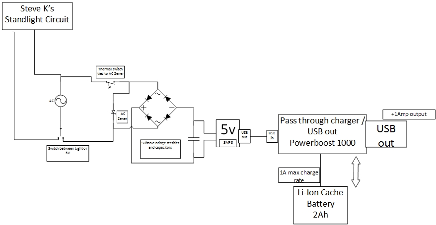
What I'd still like is USB charging during the day. I would place a STDP switch in your circuit after Q3 and Q4, removing the connection to U1. Smoothing caps will be added. Then add the 5v system after that. Would that be correct? Is D10 your

disconnecting the rectified power from the light and connecting it to a USB charger seems okay, assuming that some details are addressed.
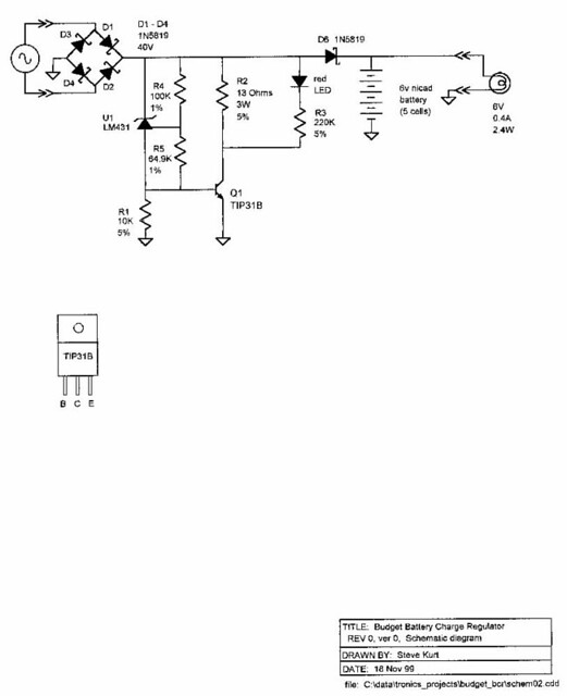
The mosfets are only rated for 30V (which was okay, because I knew there would always be 0.5A load on it). D10 was added to handle a circuit or soldering malfunction. I didn't size it to handle the dynamo power continuously.. the worst case scenario is that it'll overheat and fail shorted. There won't be any light, but at least no other parts get damaged.
You'll want to consider a bidirectional zener or other circuit that can handle the dynamo power for a continuous period of time. This is probably something you'll want to test and evaluate before committing to it.
edit: don't forget that the mosfet bridge rectifier doesn't block reverse current like a diode bridge rectifier does. This means that you can't put a filter cap on its output. You'll probably want to add a series schottky diode to the bridge's output for this purpose.

Have you had much dealings with USB charging systems? From what I gather, the more you load up a dynamo, the more power you can extract from it. But if I'm just trying to charge a battery, is that enough load? A 1A charge rate would be ok, 2A even better! I'd still want to use that Traco switch mode converter as it can take 30Vin. And if nothing is connected, does your D10 act as over voltage protection?

Thanks again for always helping Steve, its greatly appreciated!

Is this the thread where max power point tracking is discussed?? Well, go review that, and you'll see that both a big load and a small load will result in nearly zero power being extracted from the dynamo. The trick is to find just the right load, and that will be the one that lets you pull the most power from the dynamo. Of course, the dynamo's characteristics change with speed, so the "right load" will also change with speed.
As such, I can't predict how any given USB charger will behave when combined with your dynamo.
 
Last edited:

piesoup

Newly Enlightened
Joined
Oct 31, 2008
Messages
114
Location
East Anglia
Morning

I have been doing as much reading as I could on MPPT. From what I understand, the way to go is to adjust the PWM of the switching circuit to maintain the peak power. I understand doing that in principle. Using a pwm driver for the LEDs makes sense, but I cant get my head around using that for a voltage regulator. But that's just my in experience. Do you get adjustable pwm voltage regulators? I'd want a constant 5v, maybe 5.2v like the Adafruit boards to power my chargers.

From watching my lithium charger, the charger delivers low current, then ramps up for the main charge then ramps down at the end. Would this loading be sufficient? I have just realised that you shouldn't need MPPT on the 5v side. If the charger only needs 200mA, then why try and feed it any more? And the switch mode regulator should convert the extra voltage available into current.

Going back to the rectifying part of my above question, Thanks for highlighting the issues with the MOSFETs, I was unaware if that. I will have a separate circuit entirely then, I'd be easier for me! I have seen a bi-directional zener to protect against the input voltage. There was also a thermal switch attached to the zener, that when it became hot, would open the circuit, protecting the zener. This setup will be fine on the 5v circuit.

I wont need to run this circuit at low speeds, so once I'm generating at least 6v the 5v switch mode will run.

http://assets.tracopower.com/TSRN1SM/documents/tsrn1sm-datasheet.pdf
This is the one I'm looking at.

OR, would you recommend a higher voltage buck boost powered by the dynamo to power the 5v reg? Are you not doubling your losses? I have seen another circuit somewhere that uses a 12v reg to supply the 5v one.
https://www.adafruit.com/products/2190
This Verter from adafruit can output 5v 1A if supplied with 12v and enough current. If I only feed it with 5v, it'll only output 500mA.

Sorry for my ramblings, it helps write it all down !
 
Last edited:

Steve K

Flashlight Enthusiast
Joined
Jun 10, 2002
Messages
2,786
Location
Peoria, IL
switching power supply design is not a trivial subject. There is a variety of info on the web that should help explain the basics. Linear Technology has a nice primer....
http://cds.linear.com/docs/en/application-note/AN140fa.pdf

I would need to see a block diagram to know how to answer questions about the battery charger. The block diagram helps define the functionality of different portions of the circuit without needed to define what circuit is being used. This lets the designer think about the design at a higher level, making sure that all of the functions are being incorporated and paying attention to the different signals and power that need to go from one block to another.

In this design, I'm not sure (or don't recall) what the arrangement is between the buck converter that takes power from the dynamo and the battery and the LEDs.
 

piesoup

Newly Enlightened
Joined
Oct 31, 2008
Messages
114
Location
East Anglia
Morning!

I have finally read all about switching regulators, my brain is cooked! Very interesting though, there is so much to take into account. I think making my own switching reg is way out of my league, purely because of time.
I'd want to find an off the shelf component where I can adjust the duty cycle so I can have a play.
Here is a basic block diagram drawn in Visio. Is this what you meant Steve?

What I am concerned about, is that at the beginning and end of a lithium charge cycle, only a little current is drawn. I'm not sure if this is enough to extract the power from the dynamo and it may not be enough to load the dynamo to stop its voltage going sky high. I know the only way is for me to test it, but I have yet to buy everything!


Dynamo5v by Andrew Fraser, on Flickr
 

Steve K

Flashlight Enthusiast
Joined
Jun 10, 2002
Messages
2,786
Location
Peoria, IL
the drawing helps a lot!

I think that this arrangement seems reasonable. There don't appear to be any technical reasons that it shouldn't work (fingers crossed).

The biggest issue would be the selection of the buck converter that generates the 5V used by the battery charger. There are converter IC's that can handle 60V or more.... such as the LM46001 from Texas Instruments. I was hoping that they might sell a development board, but I don't see one mentioned on their web site. Mouser.com seems to offer various development boards, so that might be worth checking out. Development boards are generally intended to be used by designers for throwing together a prototype quickly. They aren't trying to be low cost, so I don't know how much more they might cost, as compared to the very low cost Chinese stuff found on ebay.

The advantage of a buck converter designed for high input voltages is that it will handle the voltages seen during typical riding. I measured 100V out of my SON dynamo at 50mph (downhill). The voltage is roughly linear with speed, so at 20mph, I'd expect to see 40V from an unloaded dynamo. If you had a buck converter rated for 60V input, you could put a 50V zener on the input (or output) of the bridge rectifier and be safe under all conditions.

This will also eliminate most or all power dissipation in the zener, so you won't have any extra load or drag. The worst case scenario would be having a buck converter rated for 20V or so. You'd need a 20V zener (or slightly lower), which might have to handle 0.5A at speed. This would mean that you'd be dissipating 10 watts when the battery was charged!!

This scenario, where lots of power is wasted when the battery is charged, is why I designed a really simple battery charger for a friend. It was just a shunt regulator, similar to a zener, but more precise. It only charged the battery at 0.5A, but would only waste 3W when the battery was charged. The battery was nicad, which could handle such crude charging methods better. It might be a way to generate the 5V for a li-ion charge controller, though, as long as the charge controller doesn't mind only having 0.5A to work with.
edit: see schematic below... [end of edit]
Not trying to say this is the preferred method, but something to know about, just in case it might help.

so... in summary, it looks like you are on the right path! :)


edit: here's the schematic for the simple battery charge regulator

5242793132_37bc5ea054_z_d.jpg


the schematic and some pics of how I built it are on flickr:
https://www.flickr.com/photos/kurtsj00/5242793132
 
Last edited:

piesoup

Newly Enlightened
Joined
Oct 31, 2008
Messages
114
Location
East Anglia
Thanks for the links, I will have a look.

I have been looking at this one mentioned by Steve too,

http://uk.farnell.com/texas-instrum...aluation-board-lm46001-synchronous/dp/2520468

Thank you for the idea of using a dev board. This one isn't too expensive. But the circuit for the LM46001 is quite simple, if I'm building up your circuit, I can do this too. Its only 5 caps, 3 resistors and an inductor. The datasheet has a pcb layout too, its almost too easy!

Your idea of using the shunt regulator made me think about automatically turning off the AC to the 5v reg with a mosfet controlled by the power boost. The powerboost has a pin that goes high when the battery is charged, I could use this with an arduino. Another pin goes high when the battery requires charging, this could turn the powerboost back on again. That should reduce the chance of seeing those high unloaded voltages. The powerboost will always be drawing a little current as the device thats plugged into the USB port will be powered, phone / gps / another battery etc. If nothing is plugged into that USB port, a switch can shut off the powerboost by putting the EN pin to ground.
Thinking about it, It would have to be controlled by the arduino too, I have to manage the battery charger and the USB out. Just as well I'm writing all this out here!

I've decided on an SP PD8X hub, I can then use it on the road and MTB bike. Better than hashing that stepper motor together. The stepper produces a huge amount of power but I doubt it'd last long at all.
 
Last edited:

Steve K

Flashlight Enthusiast
Joined
Jun 10, 2002
Messages
2,786
Location
Peoria, IL
Disconnecting the dynamo voltage from the input of the 5V converter ends up looking something like my battery charge regulator:
https://www.flickr.com/photos/kurtsj00/24171993235/

It's essentially a P channel mosfet with a small npn BJT to handle the high voltages that might be applied to the mosfet's gate. Also note the pull-up resistor that pulls the gate voltage up to the dynamo voltage, and the zener that keeps the gate-source voltage from exceeding the max allowed. The NPN has some resistors associated with it, mostly to keep the current within a range that won't exceed the zener's ratings.

Sometimes I get frustrated at how a simple concept gets complicated by all of the little details needed to keep from blowing up the parts. It's easier to accept when you look at someone else's design, since you never saw the really simple concept sketches. It does teach you to appreciate schematics.. when you look at a design, each of those parts is performing a function, even though it might not be obvious what the function is. In fact, I recall reviewing a design from a supplier and scribbling "wtf" next to a part. When asked about it, I explained that it stood for "what's the function?"... although that's not what I was thinking when I wrote it. :)
 

piesoup

Newly Enlightened
Joined
Oct 31, 2008
Messages
114
Location
East Anglia
Hi Steve

I love the WTF! I will be stealing that to use at work.

I am going to use a simple rocker switch to select between the light and 5v system. Otherwise I'll never get the build going, I'll be always reading how to do things!

On that note, what wattage resistors did you use on you standlight circuit? And what is the voltage for the small caps? I will be buying SMD components as much as possible.

Started to draw the circuit in EasyEDA and hope to get the boards made by seeedstudio. $15 for 5 boards. Not sure how much the postage is but cant be that bad. I'll pop one in the post for you too!
 

Steve K

Flashlight Enthusiast
Joined
Jun 10, 2002
Messages
2,786
Location
Peoria, IL
.......
On that note, what wattage resistors did you use on you standlight circuit? And what is the voltage for the small caps? I will be buying SMD components as much as possible.

umm.... I believe everything was 0805 or 1206 resistors, nominally rated for 0.1 watt. The current sense resistor might have been whatever I had handy, but the power dissipation is quite low, so 0805 is fine. Smaller parts might be fine too, but they just get too inconvenient to handle.
The caps?? In a 0805 package, the 0.1uF caps might be 25V or more... I don't recall what I used. Since nothing is getting above 6v or so, you'd be fine with anything rated for 10V or above. I do recommend sticking to decent quality caps... X7R or better. The poorer grades of caps just change too much with temperature or volt

Started to draw the circuit in EasyEDA and hope to get the boards made by seeedstudio. $15 for 5 boards. Not sure how much the postage is but cant be that bad. I'll pop one in the post for you too!

I'll have to bookmark the seeedstudio page. I've always just hacked my own boards, but since the new parts are so tiny, I may have to start doing proper boards. I don't think I'll have a use for your board, but you might use spares to impress friends and family, or even sell to others??

Does EasyEDA generate standard gerber files, or is it something proprietary to seeedstudio? I've been doing my home schematics in PCBExpress's schematic capture tool, but it is proprietary to them. I need to learn Eagle or something that generates general purpose gerber files that can be sent to any board house.
 

piesoup

Newly Enlightened
Joined
Oct 31, 2008
Messages
114
Location
East Anglia
Thanks for that. I hope to use the 1206 series as they are a little bigger! I didn't realise how small the 0805's are. :eek:oo:
I've found some X7R caps, thanks for the tip on them.

I haven't yet produced anything from EasyEDA, but it has online Spice called Ngspice. It does produce Gerber (or Drill) files which is nice. I have to use the online programs as I am drawing it at work on their PCs!
I'll send you the file in EasyCAD once I've drawn it so you can see.

I'll order the components and then draw up the PCB. Its getting real now!
Just need a dynamo...
 

Steve K

Flashlight Enthusiast
Joined
Jun 10, 2002
Messages
2,786
Location
Peoria, IL
1206 are huuuge! :)
0805 is pretty big nowadays too. 0603 or 0402 are getting to be typical, and there are smaller sizes than that.
I should mention that it is normal to use tweezers to handle SMD parts. I've bought some cheap ones at the local hardware store. A hobby shop might be a good source too.
However, even with good tweezers, I've had trouble gripping some 0402 parts! And once they pop out of the tweezers and land on your workbench, they are effectively lost. It's not much different from trying to handle a grain of salt. Crazy! :)

Regarding caps... the wide variety of types can be intimidating. The wiki page on ceramic caps is quite informative....
https://en.wikipedia.org/wiki/Ceramic_capacitor
and all of the manufacturers have literature that explains their products and types. Sticking to a class 1 or class 2, such as X7R is a good idea. If you want a cap for a precise application, such as a filter with specific characteristics, then something like a NPO or C0G is appropriate.

I hadn't heard of EasyEDA before. Sounds like a neat concept. Honestly, all of the various engineering tools, such as schematic capture, board layout, and circuit simulation all take time to learn and no one has the time to learn two or three of them. I've been around long enough to have used a few of each, and I'm always reluctant to spend the time to learn a new one. I've been doing a lot with LT Spice, which is pretty powerful for a free spice package. If you want to simulate anything with Linear Technology's parts, this is the only way. In a similar way, if you want to simulate with any of T.I.'s parts, you have to use their analysis tools... which aren't bad, but aren't as general purpose as LT Spice is.

I could make an argument that there's little value in using the same schematic for circuit documentation as for simulation. But that's a bit of a long story... and might depend on the specifics of what you are working on.
 

piesoup

Newly Enlightened
Joined
Oct 31, 2008
Messages
114
Location
East Anglia
Haha! They still seem tiny to me! I've got a set of tweezers and a friend has a gas soldering iron. I'll spend some time practicing first I think. Luckily the components have to be bought by the 50, so I have 49 of each spare!

Thanks for the wiki on the caps, I found it interesting reading. I did wonder why there were so many different types.

And I know what you mean about learning different systems. I used to use Solidworks, now my new company use Autodesk stuff, very similar but different enough to throw my toys out the cot every now and again!

Can I ask a few questions on the components in your circuit if you don't mind?

D2 is a schottky diode with two pins, yet the datasheet shows three, with what look like two opposing diodes.
http://www.farnell.com/datasheets/1353482.pdf

D10; what value should be spec'd here? Less than 18v to protect the CD4538?! But is that Standoff Voltage, Breakdown Voltage or Clamping Voltage? Man this is a confusing game! I'm going to read up on those three this evening to learn the difference.

L1, How important is the value of the inductor? I've found a 82uH 0.9A inductor, vs the spec's 78uH 0.82A one? The 82uH is £1 vs £10 for the spec'd one!

Thanks again!
 

Steve K

Flashlight Enthusiast
Joined
Jun 10, 2002
Messages
2,786
Location
Peoria, IL
Haha! They still seem tiny to me! I've got a set of tweezers and a friend has a gas soldering iron. I'll spend some time practicing first I think. Luckily the components have to be bought by the 50, so I have 49 of each spare!

There should be places where you can buy parts in small quantity. Here in the US, I buy from either Digi-key or Mouser.com . Either of them will let you buy small quantities... a single resistor, I think, although I don't order less than 10 (not worth the trouble to order few, and I might need them for future projects).


D2 is a schottky diode with two pins, yet the datasheet shows three, with what look like two opposing diodes.
http://www.farnell.com/datasheets/1353482.pdf

the datasheet shows a number of versions of the BAS-40 schottky. I used whatever was in my parts kit.. and may have written down the wrong version number. It's not a critical part. Any small schottky should be fine.

D10; what value should be spec'd here? Less than 18v to protect the CD4538?! But is that Standoff Voltage, Breakdown Voltage or Clamping Voltage? Man this is a confusing game! I'm going to read up on those three this evening to learn the difference.

zeners are not precision devices, and the datasheets don't make it easy to figure out. When I look at the OnSemi datasheet for the 1N5333B family of 5 watt zeners, it lists a max, min, and typical voltage at 70mA. I suppose they figure that's the current where it is best behaved. The only way to estimate what the voltage will be at 280mA (the 5 watt current) is to look at a graph a few pages later that shows the general shape of the voltage vs. current curves for the different zener values. Each value of zener has a different curve to it.

...but.... you might pick a somewhat lower value of zener. I suspect I used this because it is what I had in the parts kit (do you see a pattern here?). The voltage shouldn't get above the cumulative Vf of the four LEDs in series. My main concern was that I'd have a wire break and the LEDs would disconnect. To protect the circuitry from the unloaded dynamo voltage, I added this zener. Depending on how fast I was going, it might not be able to handle the power from the dynamo, and would likely fail shorted. Not great, but if the LEDs are already disconnected, this will still protect the circuitry.

L1, How important is the value of the inductor? I've found a 82uH 0.9A inductor, vs the spec's 78uH 0.82A one? The 82uH is £1 vs £10 for the spec'd one!

that's a fair question, and only Zetex knows the answer. Or maybe the datasheet gives a hint?? I seem to remember something like that. I doubt that this small change in inductance will make a difference. I would suggest that you check the data on your inductor to make sure it is intended for operation at 100kHz or so. Some aren't intended for use in switching power supplies and may only be characterized at a much lower frequency. The DC resistance of the inductor is another useful metric.
 

piesoup

Newly Enlightened
Joined
Oct 31, 2008
Messages
114
Location
East Anglia
Thanks for all your advice Steve. I read all the specs from the data sheets and chose different components with the same specs. The boost IC told me which inductor to choose, the one I mentioned above is fine! Mainly make sure that the resistance is as low as possible for efficiency.

I will send you my BOM in case anyone else asks you!

I have used EasyEDA to create my PCB. Is there anything I should look out for, like certain components mustn't be near others etc. Should certain traces be thicker than the norm? I've set the trace width to be 0.5mm at the moment. I've done a board with all the components on one side, the PC is trying to route a double sided one now... (Second pic)

Its just finished. I put the inductor and a few others on the underside to make it smaller. Seems to be ok. I will spend the next few days checking it before I commit to it!

SON o


Double Sided by Andrew Fraser, on Flickrne-two v01i by Andrew Fraser, on Flickr
 

Steve K

Flashlight Enthusiast
Joined
Jun 10, 2002
Messages
2,786
Location
Peoria, IL
I have used EasyEDA to create my PCB. Is there anything I should look out for, like certain components mustn't be near others etc. Should certain traces be thicker than the norm? I've set the trace width to be 0.5mm at the moment. I've done a board with all the components on one side, the PC is trying to route a double sided one now... (Second pic)

Its just finished. I put the inductor and a few others on the underside to make it smaller. Seems to be ok. I will spend the next few days checking it before I commit to it!

At one time, I had made a quick checklist when reviewing board layouts. We were using 0.2mm as the minimum trace width, so you're fine. I also used 0.25mm as the standard trace clearance. What did you use for this?
The standard via drill was 0.33mm for plated holes. The standard via pad size was 0.64mm.

A good practice is to use a ground plane. It's not always easy to implement on a two layer board. You may be able to flood some of the open space with copper and utilize it as a more robust ground network. Looking back, it's amazing what has been built without ground planes, and before a certain era (early 60's?), without circuit boards at all. Parts were soldered to terminal strips and wires were strung from one part to the other. This was back when "clock" meant something that you had to wind every day and high frequency was a radio station at 1600kHz.

I would recommend keeping the quiet stuff away from the noisy stuff. The noisy stuff is the high current paths in the switcher. Keep them all tightly grouped and keep everything else away from them. The companies that make switching power supply IC's tend to publish good guidelines on board layout and such.

You can also check out books like "High Speed Digital Design" by Howard W. Johnson. It's a bit old, but still useful. Your local library can probably borrow a copy somewhere through inter-library loans. The ISBN is 0-13-395724-1. Copyright 1993, so the definition of "high speed" has continued to evolve. "High speed" has become rather frightening, honestly! Laying out a digital processor and memory board has turned into designing a board for microwave signals.
 

piesoup

Newly Enlightened
Joined
Oct 31, 2008
Messages
114
Location
East Anglia
I'm using 0.25mm trace clearance, 0.2mm minimum SMD clearance, but in reality they are a lot further apart. The vias are now the size you have spec'd.
I've looked at using a ground plane, but EasyEDA doesn't give that option. I may see if I can get Eagle to work, that should be able to do everything.
I can make the GND traces wider pretty easily.

So the noisy lines should be kept away from the rest. Would these be the ones highlighted in the picture?
having a read up on PCB design for SMPS now.


Capture2 by Andrew Fraser, on Flickr

Capture1 by Andrew Fraser, on Flickr
 

Steve K

Flashlight Enthusiast
Joined
Jun 10, 2002
Messages
2,786
Location
Peoria, IL
yep, that's basically it. As the drawing of the current loops in boost converters suggests, these loops should be kept small.

In this case, the input cap, inductor, Q10 transistor, and sense resistor should all be kept very close and in a small area. I think Zetex had this in mind when they chose the pin assignments on the IC, because they all seemed to fall into place for me. IIRC, I didn't have to do very many jumper wires for these parts... I could just cut slots in the copper and get everything to hook up well.
this was my rough layout....
15675658439_9c733ed2c5_z_d.jpg


and this is the built-up board.....
15861029022_82a1528814_z_d.jpg


The Zetex IC is just to the right of the inductor, and the transistor is right above it, with the base and emitter connected to two of the IC's pins. I did have to lift pin 2 of the IC and run a wire to it... just no way to cut slots small enough with a Dremel tool.

The one detail of the layout that is a significant deviation from the ideal layout is the location of C7. It should be located very close to the inductor. It will be providing the initial current fed into L1, and will absorb the energy from the wiring inductance when the inductor current decreases. There are a lot of weird little spikes and oscillations in a switching power supply, due to the assorted stray inductances and capacitances, and having sufficient bypass caps and having them located optimally helps out.
 

piesoup

Newly Enlightened
Joined
Oct 31, 2008
Messages
114
Location
East Anglia
Thanks for those tips!

I had to send the last post quickly and hadn't finished. I was going to list the same components as you, so I must be learning something! I will look for that book, it must be around somewhere online as a pdf.

I have rearranged my board taking note of the switcher and the nearby current loops. Green is the input loop, pink is the power loop. Looking at putting all the switching bits on the bottom layer now. This is it so far!

Loops by Andrew Fraser, on Flick
 

Steve K

Flashlight Enthusiast
Joined
Jun 10, 2002
Messages
2,786
Location
Peoria, IL
Looks much better! :)
I don't see the inductor, but assume it's not far from here?

I do find myself yearning for a more robust ground network. Hard to say what is really required. One rule of thumb that was more common in the days of really simple single-sided boards from decades ago is that each section of circuitry should have its own local ground network, and then those networks should be connected at one point. The general idea is that all of the current surges that are happening in the boost converter should stay in that area. This keeps it from flowing in the ground traces of the other circuits and causing voltage drops across the ground traces. The common term is "star" grounding.

Regarding the "High Speed Digital Design" book being available as a pdf... I haven't looked for it. I got a copy from my employer's library. Any public library can do interlibrary loans, where they can borrow a book from some library that has the book.
Alternately, companies like Linear Technologies, Texas Instruments, Analog Devices,etc., have pretty good tech info on their web sites and should have some info on board layout. Finding the info on the web site is not always so easy, though.
 
Top